(Essentially it's simply replacing a Sanken SI-1725HD dual-channel audio power amplifier module with two single-channel LM-3875T ICs.)
This isn't a restoration, where it's returned to original condition, that isn't possible without particular parts. If you'd had an amplifier repaired during its heyday, they were repaired into working condition, not original factory condition. And I'm not sure you'd really call this amplifier “Hi-Fi” in it's original or repaired condition. Although the amplifier ICs have specifications of 0.06% total harmonic distortion, and a 0.006% claim with intermodulation distortion, it's going to depend on the design of the entire amplifier (including all the other circuitry around them), and is often a claim made under certain optimum conditions rather than a measurement that holds true under all normal operating conditions. If it were really true, then all Hi-Fi amplifiers would sound the same (faithfully reproducing the sound as originally mastered by the studio), and they don't. Anything that makes one amplifier sound different from another is a distortion of the signal.
Realistically, most stereo amplifiers of similar designs (based on simple pre-amp stages and an off-the-shelf power amplifier module) are quite good, usually better than most people's hearing, and buying a really good set of speakers is the best thing to spend money on when you're concerned about good sound quality, followed by a reasonably good turntable (if you were into vinyl records). You don't need to spend tens of thousands of dollars on a stereo system to have good sound. Leave that kind of thing to people who have more money than they need and spend similar amounts of money on their artwork and furniture.
A bit about these amplifiers
Both of these Rotel amplifiers use the same amplifier stage, the difference between them is the number of radio receiver bands. The 500 model only has AM & FM radio receivers, whereas the 500SL also has short-wave and long-wave receivers. Both have moving-magnet phono inputs, and tape monitor loops. Neither of them are spectacular devices, just run-of-the-mill home stereo amplifiers aimed at people who didn't want a cheap plastic box three-in-one stereo system. But I'd had many years of enjoyment out of it, and it's certainly worth spending $25 dollars on to replace a part.
There's only really a couple of things that I disliked about the amp—there's no auxillary inputs, and no speaker protection (not even a switch-on/off de-thumping mute circuit). But one thing I particularly liked about this amp, and missed on my other amplifiers, was the mono button. I used the amplifiers to monitor editing of audio/video productions, and you want to be able to easily check mono versus stereo sound quality. Plus it makes the playback of mono records on a stereo turntable a bit less noisy. And, yes, I still have a few mono records.
My other amplifier's mono buttons only affect the FM receiver. Stereo FM has worse signal-to-noise than mono, so it's useful to be able switch off the FM stereo decoder when receiving a low signal strength channel. And, like most receivers, the mono button also disables the auto-muting when not tuned into a station. But the Rotel's mono button did all of that, as well as monofying all audio signals, not just the radio.
What went wrong
Long ago my RX-500 amplifier's SI-1725HD audio power amplifier output stage module failed, and burnt out the woofer in one of the speaker boxes. The module put the full high voltage supply rail through the speaker, and destroyed it in moments. The positive rail, if I remember correctly. I always wanted to fix it, but didn't have the parts, and I'd just replaced it with a newer and better amplifier, as a matter of expediency. Now, over thirty years later, I've finally gotten around to doing it.
For what it's worth, its replacement died about a decade later (a Sherwood amp), and I've still got that in the shed (where atmosphere has taken its toll on the metal lid). But before it died, I used the Rotel as a tuner for it (with the Rotel's power amp module removed from the board), as the Sherwood was purely an amplifier. The Sherwood got replaced with second-hand Panasonic home theatre amp, which I don't think sounded as good. I seem to recall that the Sherwood developed a similar output stage fault, but that amp has discrete output transistors (probably FETs), so ought to be repairable, but it also developed another fault in its muting control IC (unfortunately a part with no obvious replacement). Though, upon reflection, I think the muting IC went bad, and took out the output stage, or drove it hard into saturation. Either way, without the proper muting control IC, it'd need quite a redesign to make it operational again, I couldn't find a schematic diagram, and I found the Panasonic amp on sale at a good price. And the Panasonic went wonky many years later, too, though that was just bad soldering where the speaker terminals went into the main board.
If you ever hear a loud hum or buzz when you turn on an amplifier, switch off immediately and don't turn it on again with the speakers connected. Un-wire them, and measure the amplifier's speaker output with a DC meter (do both channels, separately). If it's something like 30 volts (or more), that's this kind of fault. Ordinarily amplifiers should have zero volts DC on the output, or very very close to zero (only fractions of a volt).
The amplifiers use a module for the PA stage, and that kind of failure is common in these modules, as well as discrete supplies. Either one of the output transistors goes short-circuit to one of the supply rails. Or, one of them goes open circuit, and its (still working) opposite partner pulls the output towards the other supply rail. In any case, you have to replace the whole output module, and perhaps a speaker if you weren't quick enough to turn the power off (I wasn't). With discrete-circuit amplifiers, you'd only have to replace the output transistors and/or their drivers. It's usually an output stage failure, because components that have to deal with high currents, or get hot, have the toughest life.
In the past, this would have been a moderately easy repair. You just replaced the output module (which did involve unsoldering 16 pins, hence why it's not a completely easy repair). But they haven't been available for many years. You may be able to find an equivalent module, but that may be just as hard. And I can't find any specs for the Sanken SI-1725HD module used in this amp, to make a good judgement call about it. I recently found the service manual schematics for the amp, which gives some clues about the pinouts, with no real details about the module, but does have enough information about the circuitry around it to make some educatated guesses for replacing it with something else.
The repair
The amplifier's basic specifications are that it's something like 25 watts per channel. The high voltage supply is around plus and minus 30 volts DC. Yes, I know those figures don't quite tally up, but I'm just going by the information I have to hand (the sales blurb about the amp, and measuring the supply voltages), and there's the efficiency of the design to take into consideration, too. So you just need to find a module, IC, or ICs, that can run from those voltages, is within that power range, and doesn't need any fancy EQ or bypassing (well you can use one that does need it, but then you're going to have to build all the extra bits, if you do).
Since I recently repaired the audio power amplifier output stages in my Technics U90 organ for the same fault (but in a Sanyo STK465 module), using a pair of single-channel LM-3875T ICs, I figured I'd try the same repair in this amplifier. I don't know how available those parts still are, as I just wiped out the left-over old stock from a couple of my local electronics shops. But anything similar will do. And you can find the specs for those ICs, to find similar parts to them.
The LM-3875T chips just need plus and minus DC supply rails somewhere between 20 and 80 volts (but typically 35 volts), an audio in, a ground reference, some negative feedback resistors (the ones built into the amplifier being repaired, between its output and negative audio input, should do), and an output connector. Likewise for many other similar ICs.
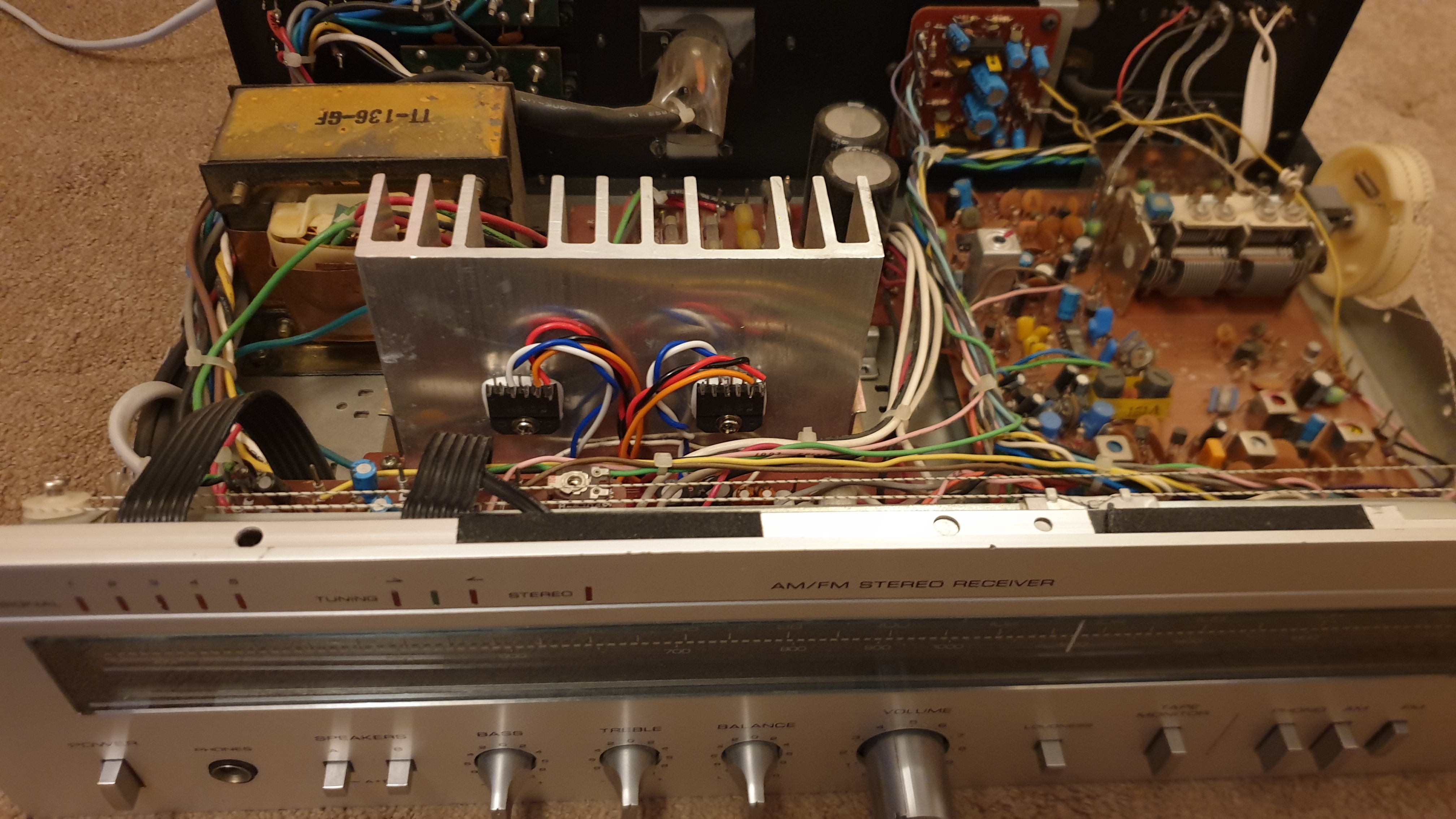
They're all present on the Rotel amplifier, but the pinouts are different, you'll have to use flyleads between the circuit board and the new chips. Simply bolt them to the two screw holes that the original module used on the heatsink, with heatsink compound between them and the heatsink.
NB: If you buy fully-plastic-encased LM-3875T ICs, they're already insulated. But if they have an exposed metal back, it's connected to −VCC, and you'll need to use an insulating washer between the IC and the heatsink (with heatsink compound between ICs, washers, and heatsink), as the heatsink is directly connected to the chassis.
And that's pretty-much all you have to do, other than some testing (with the speakers disconnected). Although you may find that, due to the age of the amplifier, that you may have to clean the pots, the switches, and you might have to replace some of the electrolytic capacitors for being dried out. I wouldn't go mad doing this, concentrate on the DC filtering caps, they're the ones that have the hardest life. Many of the coupling caps will still be good enough, even if not 100% as good as new. I don't think any of mine needed replacing, though I might swap the two on the phono inputs (they seemed a bit touch-sensitive).
Mine had a tiny bit of AC hum in the left channel, but that's due to the power transformer being so close to the left power amplifier chip, the high voltage supply was fine. Different chips may be less susceptible, or rotating the chip around the mounting hole may help (having long-enough flyleads to experiment will help). I could hear it in some very good headphones with the volume control turned all the way down, but it's well below the sound level of any actual music you'd listen to.
I've had the same problem with other amplifiers. It's why you find that some amplifiers have the mains transformers in strange positions, or in a separate box (trying to minimise its electro-magnetic emanations from getting into other things). And why I don't advocate going to extraordinary lengths to restore the amplifier; it wasn't super-fantastic to begin with (it was the kind of product that would have sold for a few hundred dollars, not a few thousand).
Of course, the amplifier's specifications will be somewhat different, now. So I wouldn't try driving it too hard. The original design would have taken stability into mind based on the parts that it was actually intended to have. Likewise with the heatsinking. Having said that, you rarely drive an amplifier at full pelt, just a few watts are very loud in a small room. And many amplifiers could never continously run at their claimed ratings, they'd overheat.
Left amplifier replacement
| SI-1725HD pins | Purpose | First LM3875T pins (left speaker driver) |
|---|---|---|
| 1 | + audio in (left channel and ground reference) | pin 7 (+ audio in) |
| 2 | − audio in (right channel negative feedback loop, and tone controls) | pin 8 (− audio in) |
| 3 | unknown | not connected, not applicable to LM3875T |
| 4 | ||
| 5 | ||
| 6 | B− | pin 4 (−VCC) |
| 7 | speaker output (left channel) | pin 3 (speaker output) |
| 8 | B+ | pin 1 (+VCC) |
| 9 | B+ | not connected, the other LM3875T uses these pins |
| 10 | speaker out (right channel) | |
| 11 | B− | |
| 12 | unknown | |
| 13 | ||
| 14 | ||
| 15 | − audio in (right channel) | |
| 16 | + audio in (right channel) |
Right amplifier replacment
| SI-1725HD pins | Purpose | Second LM3875T pins (right speaker driver) |
|---|---|---|
| 1 | + audio in (left channel) | not connected, the other LM3875T uses these pins |
| 2 | − audio in (right channel) | |
| 3 | unknown | |
| 4 | ||
| 5 | ||
| 6 | B− | |
| 7 | speaker out (left channel) | |
| 8 | B+ | |
| 9 | B+ | pin 1 (+VCC) |
| 10 | speaker output (right channel) | pin 3 (speaker output) |
| 11 | B− | pin 4 (−VCC) |
| 12 | unknown | not connected, not applicable to LM3875T |
| 13 | ||
| 14 | ||
| 15 | − audio in (right channel negative feedback and tone controls) | pin 8 (− audio in) |
| 16 | + audio in (right channel) | 7 (+ audio in) |
I've written “unknown“ on some pins where I don't know what the pins are actually used for on the SI-1725HD module. On the amplifier, they're AC coupled to ground, or another pin, so I can only assume AC bypassing and coupling. The LM3875T doesn't need them, so they're just left disconnected.
For noise reduction, I've twisted the + & − DC supply leads around each other. And I've done the same thing twisting the + & − audio input leads around each other.
A bit about the SI-1725HD & LM3875T power amplifier modules
Like many of these devices, they're a differential input device (they're virtually an op-amp with a high-current, high-voltage, output stage). That is, one input pin operates in opposition to the other, producing a positive or negative output, depending on which input has the greatest signal, as well as its polarity. And if a common signal is applied to both of them, it cancels out.
While you might think they could be used as a balanced input, that's not the case. With op-amps, the positive input has a high impedance (could be many hundred-thousands of ohms, or even many megaohms), and the negative input has a very low impedance (virtually 0 Ω). As it stands, the device is only a voltage device, and a balanced input needs equal impedances. You'd need external components to try and create the same impedance to both halves of the source, and also take into account the components inside the op-amp input stage. And for good CMMR (common-mode rejection ratio), they need to be very closely matched.
But none of that is required, here, because the drive signal is only being applied to one of the inputs, the other is being used for negative feedback (as gain control, and with the tone controls in the middle of that negative feedback loop).
Just like general-purpose op-amps, they have a very high gain and need external negative feedback resistors (between the output stage and the negative input stage, perhaps also to ground), to set the gain. Some other power amplifier devices have fixed gains. It's been set internally, though may provide some way to externally reduce the gain (if required). That could be by using negative feedback, or there may be some gain pins that you pust a resistor across, perhaps AC-coupled through a capacitor, too.
A bit more about the Sanken SI-1725HD power amplifier module
I'll never know why the original Sanken module died, but can make some educated guesses, though limited by there being very little data available about the module. It's long out of production, and there's only a few badly scanned pages of specification sheets on it that I can find on the internet. None of them have much in the way of useful information on the module.
Whenever the Rotel amplifier was turned on, there was a loud “bong” noise from within the casing. That would mean that heavy current went through the power transformer, and its magnetic fields was strongly affecting the metalwork of the amplifier chassis. But with the module removed, and with it replaced by LM3875T chips, it doesn't do that any more. So my guess would be that the SI-1725HD module could have a push-pull output stage that both halves would come on together (they shouldn't) at power-up, causing heavy current flow. Or that one half came on very hard, at least. If the amplifier was powered on with the speakers still switched on, there'd be a very prominent thump. There was even a strong pop noise if the speakers were switched on shortly after powering up the amplifier. Likewise for the speakers loudly going “crack” at power down. The input stage is AC coupled, and ground referenced, but the output stage is DC coupled to the speakers. So I don't think the module powers up and down cleanly, or symmetrically, and turning on hard would be a stress on the device.
And there's no prizes for guessing that heatsinking may be inadequate, and the device probably roasts itself over time. The amplifier's heatsink is rather small, it's buried in the middle of the chassis, hemmed in on all sides. There's only a small grill underneath the heatsink, with a larger one in the top of the casing, for airflow. The amplifier's feet are small, so there's limited airflow below the chassis, and stereo shelving systems don't leave much room around the amplifier, either. Also, there's no fan to force air through it. Not to mention that we live in a hot country, just to compound things for an amplifier that was designed in a cold country (European designed TV sets suffered badly from heat stress in Australia, too).
Delving further into the overheating situation: The heatsink compound spread between the amplifier module and the heatsink is designed to make the transfer of heat more efficient, but it dries out over time and becomes ineffective. Given the wrong circumstances, it could actually impede heat transfer. It's a very long time since I removed the dead module, but I don't recall the compound being moist (like other equipment I've worked on), it was rather tacky.
There is a school of thought that says performing maintenance on heat-sensitive equipment by replacing heatsink compound periodically, even when equipment appears to be operating flawlessly, before any breakdowns happen, may be a good thing to do. Once or twice a year I open up computers and remove the dust and fluff that accumulates around their heatsinks, knowing that causes a problem with heat transfer. I may start inspecting fan-less equipment, too, to see how the heatsink compound is faring. Replacing it is a pain, but far less painful than looking for replacement amplifier modules.
Written by Tim Seifert on 2 November 2022, and last updated 7 October 2023.