While tracking down an intermittent fault, I sketched out various parts of the circuit, since I don't have the service manual, and couldn't find a schematic on the internet. I haven't filled in all the component part values, since I didn't need to know them all. And I've only made educated guesses about whether a transistor was PNP or NPN, based upon its place in the circuit.
I'm not intending to go through and note every component value. It'd take too long, I'm not being paid for it, and it's awkward to do on a board that's partially captive to other things. I don't like unplugging ultor caps, or CRT neck connectors, it's too easy to break something. But if you need to know the value of a specific component, because you can't read it anymore (e.g. burnt out resistors), let me know, and I'll see if I can tell you. I have no ideas about what you might replace the flyback transformer with, nor any other coils, should it be necessary.
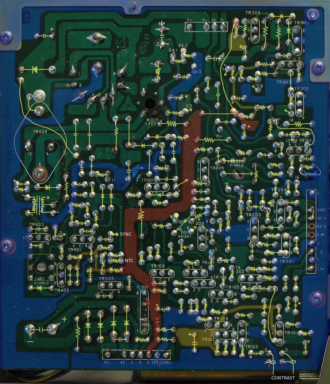
I haven't uploaded this sketch, it's not easy to do at the moment, but I have uploaded a board overlay picture.
Some monitors can't reduce the scan height enough to be set up for underscanning, or even a normal picture. Soldering a 10kΩ resistor over point 15 to ground (over the bottom half of the height pot voltage divider, just below TR301), will give you sufficient range. Or, a slightly lower value, if you want to set the monitor height to suit 16:9 video. You can see the resistor on the photo of the circuit board.
If setting the monitor up for underscanning, you may notice that the centring and rotation of the raster is quite a bit off. You'll need to carefully slacken the yoke clamp and wiggle the yoke, slightly, to adjust rotation. And, even more carefully, break the seals holding the centring magnets at the back of the yoke assembly. Centring and rotation are affected by external magnetic fields, including the planet Earth's. Rotate the monitor around while making adjustments (face it north, east, south, west), and adjust for the average best results for all monitor orientations. Or, make your adjustments with the monitor facing the same way that you will mount it.
A brief poke around with a CRO suggests the CRT is grid driven, rather than cathode, since there's only blanking on the K wire.
The video does not appear to be DC clamped or restored. The diode in the video output section seems to be part of the blanking circuitry.
There is no focus control, so a soft image suggests a bad CRT or high tension supply. The monitor has somewhere around 800 lines of resolution (tested using a computer generated test card, so it's an estimate). i.e. It's normally high resolution, with sharp focus, and with a wideband amplifier, rather than a horribly overpeaked low bandwidth video amplifier. Even after twenty years, a set that hasn't been abused, nor had faulty parts, will still give a sharp picture. On that note, running CRT monitors with the brightness and contrast set too high wears them out much quicker. If the picture is going out of focus as you turn up the controls, either you're turning them up way too much, or the tube is worn out (if it defocuses while only showing a dim picture), or the tube voltages are wrong.
If the voltage regulator has gone bad, it's probably easier to just replace the entire circuit with a three-terminal regulator (remove the thick film IC and the back panel mounted transistor), but check for dry joints around the regulator components, first. The unregulated DC is about 27 volts, the monitor requires 15 volts regulated, and uses about 800 mA (measured while showing a medium grey blank raster). The large transitor mounted on the back panel does heat up the panel, but it should not get painfully hot. I put the replacement regulator IC on the back panel, in place of the original transistor.
There are a few NTC (negative temperature co-efficient) resistors in the circuit (the big green resistors, and a few small round ones that look like fat ceramic capacitors with a sharp edge, rather like a coin).
There's a tendency for bad corrosion around the centre of the board that gets worse with age. You may need to bridge across the tracks in several places.
A tally light can be added using one of the circuits described on the tallies page. If you carefully remove the dress panel behind the front-panel knobs, you'll find two un-used holes in the plastic chassis. You could fit a 1 cm LED into one of them (bend and insulate the legs, and pass a wire over the chassis behind the hole, making sure it won't get pinched), and very carefully drill a hole through the dress panel (wide enough for the LED to poke through, but be held back by the flange at the back of the LED).
There are X's drawn next to components that weren't installed on our board, and next to PCB pads that have nothing soldered to them. The same board was used in more than one model of monitor, some with external sync inputs.