Recently I had to replace a Sanyo STK465 audio power amplifier module in my Technics organ, but they're no-longer made. The last time I had to replace one, over a decade ago, you could still scrounge them up, but now the only things you can find are ones removed from old equipment (which may not be reliable), or potentially counterfeit ones from China on the internet (which may never work, or may work for just long enough that they last past the time-period fleabay lets you return items).
Your alternatives are building an equivalent from other components, or trying to find an alternative IC or module to do the job. The latter being easier than you might think. The STK465, and a few lesser-wattage similar modules, are nothing particularly special. It's just an amplifier in a block, with some in and out pins, supply pins, and a few other pins which probably are to do with gain selection and bypassing (inapplicable to different amplifier modules). It's why they were so common in various audio equipment, the manufacturers hardly had to design anything, just wire into place with a few extra components.
What typically goes wrong with them is either an open-circuit or short-circuit in the output stage (because it has to deal with the most current). Either situation can result in the full supply voltage going through the speaker coil, which will burn it out in mere moments. A fuse won't protect against this, so separate DC protection circuitry is a good idea, but I don't have any advice to offer on this at the moment.
I've found that the LM3875T IC (a component I could directly buy from a real electronics supplier) can be used as an almost direct replacement. It's a single-channel IC, so you need two of them to replace one two-channel stereo STK465 module. And the pinouts are different, so you'll need to run flyleads from the IC pins to the rest of the circuit. But I didn't need to change any of the components on the original amplifier. Five short flyleads, and the job's done (positive and negative DC power, positive and negative audio inputs, and an output lead).
I did add some more bypass capacitors for stability against oscillation, but other amplifiers might already have enough of them in place.
STK 465 pinouts
- + audio in (channel 1)
- − audio in (channel 1)
- ground (input stage channel 1)
- bypass/gain? (channel 1)
- −VCC (output stages of channel 1)
- audio out (channel 1)
- audio out (channel 1)
- +VCC (input stages, both channels)
- +VCC (output stages, both channels)
- audio out (channel 2)
- audio out (channel 2)
- −VCC (output stages of channel 2)
- bypass/gain? (channel 2)
- ground (input stage channel 2)
- − audio in (channel 2)
- + audio in (channel 2)
Pins 3 and 14 would normally be joined together (grounds).
Pins 5 and 12 would normally be joined together (negative supplies).
Pins 6 and 7 are the junction of a push-pull output stage and need to be joined together. In my amplifier, they're directly joined. In the STK465 specs sheet, they're joined by a 0.33 Ω resistor, with the speaker output taken from pin 7.
Pin 8 is the +VCC for the input stages, it could be derived from the main +VCC (going to pin 9) with some extra filtering for stability. Such as through a 100 Ω resistor with a 100 μF capacitor to ground.
Pin 9 is the +VCC for the output stages.
Pins 10 and 11 are the junction of a push-pull output stage and need to be joined together. In my amplifier, they're directly joined. In the STK465 specs sheet, they're joined by a 0.33 Ω resistor, with the speaker output taken from pin 10.
Separate power and ground terminals would allow for more complicated supply filtering, for amplifier designs trying to minimise interaction between the channels. Though that kind of HiFi design technique is generally more high-end than the kind of products that would use this module.
LM3875T pinouts
- +VCC
- not connected
- audio output
- −VCC
- not connected
- not connected
- + audio in
- − audio in
- not connected
- not connected
- not connected
Both amplifiers are normally used in a circuit with negative feedback components going from the output, to the inverting input (− audio in), then to ground (together they set the gain). So, to fit a LM3875T to where a STK465 used to be:
- Connect the new LM3875T's +VCC (pin 1) to where the old STK465's +VCC was (pin 9).
- Connect the new LM3875T's −VCC (pin 4) to where the old STK465's −VCC was (pin 5 or 12).
- Connect the new LM3875T's non-inverting input (pin 8) to where the old STK465's inverting input was.
- Connect the new LM3875T's non-inverting input (pin 7) to where the old STK465's non-inverting input was (pin 1 or 16).
- Connect the new LM3875T's output (pin 3) to where the old STK465's output pin was (pins 6 + 7, or pins 10 + 11).
You might have noticed that there's no ground. Generally a ground reference will be made through one of the input pins through some resistors. This will be part of the original amplifier design. The STK465 had a ground pin because it was part of the input stage's power supply circuit, it wasn't just an audio signal reference point.
General info
Depending on the particular chips and module used, the device may be electrically insulated from the heatsink already, or you may need to use an insulating spacer between them. The STk465s, that I had, pins were electrically isolated from their backplate. The LM3875Ts that I have, were fully plastic encased. Its back is electrically insulated, and probably not as thermally conductive as a metal backplate. The alternative to insulating an IC from the heatsink, is to isolate the heatsink from any other part of the circuitry, and to enclose the circuitry so that the heatsink cannot be touched.
Many other ICs of a similar design could be used instead. While it's hard to find a good spec sheet for a STK465, the LM3875 is readily available, and that can be used as a comparison with other alternatives. They are the same as a basic op-amp (operational amp) circuit, the major difference being that these devices can supply sufficient current to directly drive a speaker.
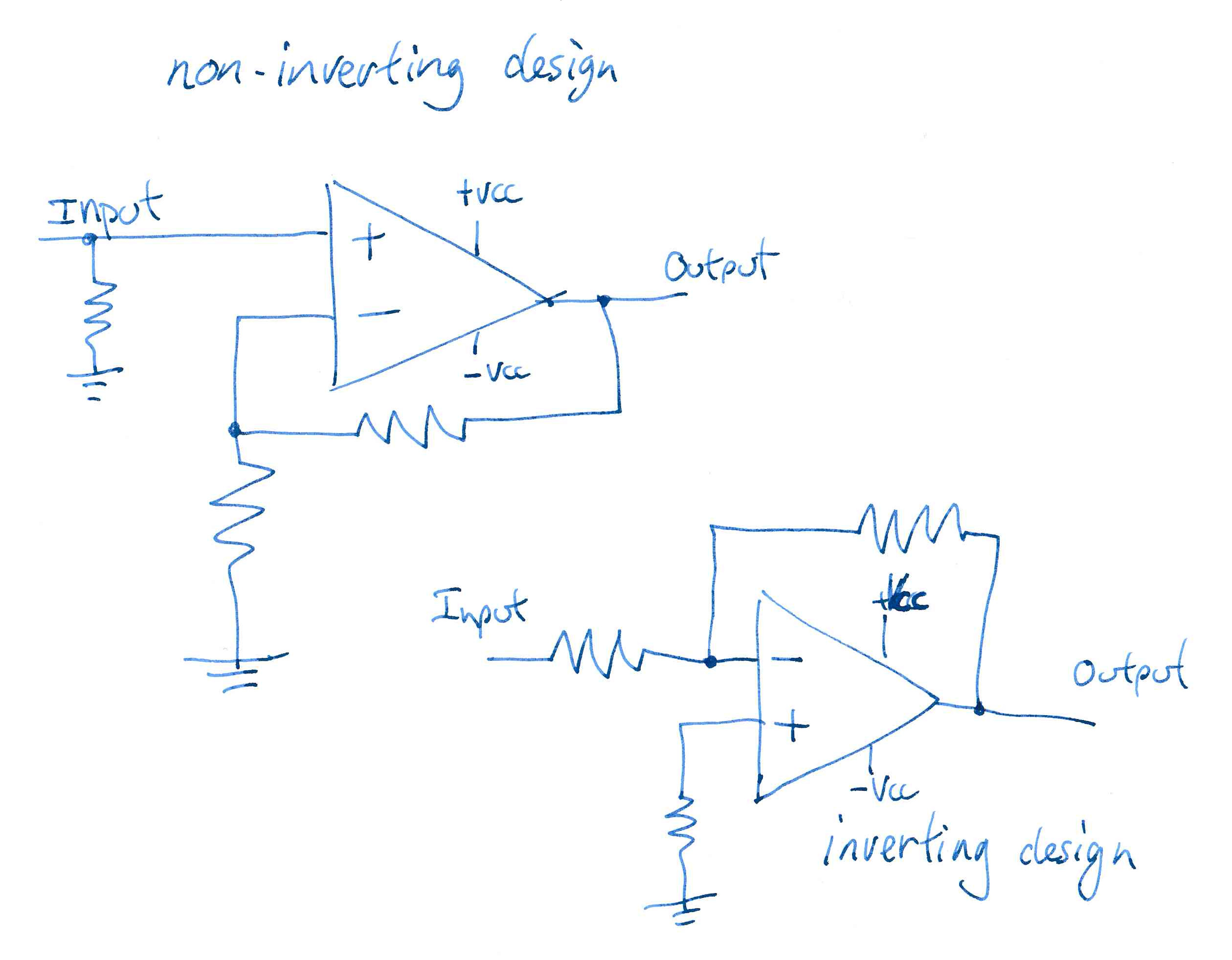
With ideal components, the positive input is very high impedance, and the inverting input is almost 0 Ω. If you tried feeding a signal directly into the inverting input it would heavily distort, and possibly destroy some components.
In these examples, the resistors on the positive input provide a reference to ground.
The two resistors attached to the inverting input form a negative feedback circuit, the ratio between them setting the gain. On the non-inverting design, the ratio is solely controlled by the two resistors (it's a voltage divider between output and ground). But with the inverting design, the impedance of the source driving the amp is part of the equation (it's a voltage divider between the output, the input resistor, and the source impedance to ground). This makes predicting the gain a bit more difficult (it'll depend on what you know about the source).
If considering other devices than these two, it's worth remembering that some audio amplifier ICs already have a preset gain (in essence, the feedback resistors are internal). And some experimenting may be required to see if the device has enough gain. You may need to change the feedback resistors in your existing circuit. And if you're adding external negative feedback resistors to a IC that already has internal ones, the results may differ from what you expect.
And some may have input protection components to protect against being over-driven. So care has to be taken to ensure your source is of a suitable level. But these two devices seem to be similar enough that no modifications to existing circuitry proved necessary in my case.
Powering
It's typical for power amplifiers to run from unregulated supplies, with a simple bridge rectifier and large filter caps to provide a simple DC supply. With some smaller value caps close to the amplifier circuits to prevent oscillation.
The large value caps are going to filter the 100 Hz rectified AC frequencies, smaller value caps will filter audio and ultrasonic frequencies (providing a low impedance path to ground, to shunt any oscillations). Even though they're all directly in parallel, each has a different reactive response to different frequencies. Hence why one huge cap can't do the whole job by itself.

It's also typical for audio amplifiers to use completely separate DC supplies for any pre-amplifiers. While they could be a regulated supply derived from the large supply to the power-amps, they're usually taken from a separate set of taps on the main transformer, or from a completely separate transformer on some Hi-Fi designs, and of a lower voltage (pre-amps need less voltage and current to do their job). And being a regulated supply from a separate source reduces the risk of oscillations, or other interference from the power amplifier, causing signal distortions.
Other alternatives
There's a variety of all-in-one power amplifier ICs, many of which could be used, instead of the LM3875T. All you need to do is find something similar enough. There's nothing particularly special about this module, nor the replacement IC that I used. About all you need to look for is similar power ratings and power supply requirements.
The other approach is to build an amplifier using discrete components, but then you'd have to design it, or find a ready-made design. The advantage of discrete component amplifiers is that if one transistor goes bust, you can replace it. And you'll probably have an easier time finding a replacement transistor than a replacement IC (designs fall out of popularity, and stop being manufactured). But to do the job properly, your parts should match very well.
The disadvantage of discrete component amplifiers is that parts don't always match very well. That most of the parts are temperature sensitive, and you really need to bond components together with opposing characteristics, so that as one part's performance changes in one direction as it gets warm, it has a counteracting part that pulls things back in the opposite direction as it warms up. The need for compensation builds in complexity, and makes things even bigger. And as well as simply taking more room to fit all the parts in, that's more opportunities for interference to get in, and for the layout of components to affect its characteristics.
The advantage of an integrated circuit is that all the internal component parts should match very well, there is good consistency between circuits (one IC should be extremely similar to another IC), thermal compensation is built-in (or should be), the device is compact, most of the complex parts of an amplifier's design is internal to an IC, and only simple circuitry is needed outside of the IC.
You can build quite good audio amplifiers based around a power amp IC (or module) and a basic pre-amp. Around that, it's the power supply, and the controls (volume, tone, input selector). Many of the old-school domestic amplifiers were built like that. Adding digital inputs, remote controls, etc, is a more modern thing that really doesn't add anything to the sound quality of an amp. They can actually bring in various problems (added distortion from going through an electronic input selector instead of just a mechanical switch, noises caused by the remote control circuitry and illuminated displays, amplifiers that only have bare functionality without the remote control).
DC protection
The DC output from an amplifier should be zero volts. That means when the amplifier is producing no sound, there should be no voltage on the output; and when the amplifier is producing sound, only AC voltage should be output. Tiny amounts of DC (e.g. less than a volt) mightn't be a problem, but still could be. Larger amounts of DC causes distortions in the speaker, even larger amounts burn them out.
DC detection, or speaker protection circuits, detect a DC voltage on an amplifier output and disconnect the speakers to protect them. Detecting the unwanted voltage isn't too hard, it's disconnecting the speakers that's the harder part of the equation. It has to adequately isolate them, and needs to do so reliably. It can be part of the amplifier's design, or it can be an external device between the amplifier and the speakers.
Mechanical relays can weld the contacts so they won't disconnect, or the contacts mightn't spring apart wide enough to do the job, or their contacts can get grotty and not make a good connection under normal circumstances.
An electronic switch could introduce distortions (if audio has to pass through it for normal operation), and it could fail just as easily as a transistor could fail in an amplifier (the cause of a DC fault). I'm beginning to think one approach is for the protection circuit to short out the speaker when a DC fault is detected, and deliberately blow the speaker fuse. If you have DC on the output, the amplifier is already faulty, and you're only concerned with saving the speaker.
Still another approach is to have the protective circuit cut off the high voltage supply to the power amplifier. That's an easier on/off situation to handle; and since audio isn't going through the switch, it shouldn't be a potential cause of distortion.
Speaker protection can go beyond DC detection, if you want. You can have sensors to detect if the speaker is being driven too hard. You can have dethumping circuits which mute the speakers when the amplifier it switched on and off.
Is there a need for speaker protection circuits? Over the last few decades I've had three amplifiers develop a fault that put the amplifier's high voltage supply through the speaker. At least two of those faults burnt out a speaker voice coil, I seem to remember that I turned the amp off quick enough to save the other speaker. In all cases my amplifiers exhibited the fault just as they were switched on. The opposing argument is that for the best part of 30+ years, the amplifiers didn't have any faults.
For what it's worth, the speaker fuses in the output of an amplifier may not protect the speaker. Their job is mostly to try and protect the amplifier should the speaker wires get shorted together. But they mightn't even manage to do that. Your amp still might get damaged under those circumstances, but is much less likely to also catch fire.
Written by Tim Seifert on 22 October 2022, and last updated 15 November 2022.