Warning
This modification allows you to use traditional 48 volt phantom or battery power. But when battery powering the mike, insert a battery and ensure that phantom power is not applied to the mike. And, conversely, when phantom powering, ensure that you remove the battery and insert the shorting shunt into the battery compartment. Failure to follow those instructions could damage the mike with excessive voltage, and possibly cause destructive damage of the battery.
This is not a project suited to those who are not familiar with electronics, soldering, nor willing to risk damaging their mikes. You should be able to read the diagrams and understand these instructions without any further help. This is a description of a modification that works, so you don't have to experiment. If you find this too daunting, you have several options: Continue using batteries, find someone to modify them for you, or buy new microphones.
Having said that, this modification only involves changing a couple of circuit components around, and adding a few more, in the backend of the mike (specifically, between the battery chamber and the XLR), the headamp and capsules are not modified (so you can swap them around in exactly the same way as you would with the original mikes), and there are no mechanical modifications to the mikes. Most of the difficulty is careful disassembly, and soldering. The mikes continue to be operational exactly the same as they used to be, minus the need to use batteries, but they still can be battery powered, when you want to. This mod is designed to be simple and convenient, and not degrade the mike in any way.
A couple of similar Nakamichi microphone kits
In the 1980s/1990s, there were two very similar microphone kits made by Nakamichi. The kits were a microphone made with swappable (CP-1) uni-directional, (CP-2) omni-directional, and (CP-3) pinpoint omni-directional microphone capsules, a headamp for those capsules, a (CP-4) super-directional shotgun capsule with a built in headamp, and two different back-ends (a CM100 1.5 volt battery powered backend, and a CM300 9 volt battery powered backend). At the time I bought mine (brand new CM300s with CP1, CP2, and CP4 capsules), I was told there was a phantom powered backend, but I have no details.
Interestingly, the same capsules appear to be used with either backends, yet mine do not work if the battery power is somewhere below 7 volts (a very low signal output level, and badly muffled treble response). But, looking at the backend schematics, they're not sufficiently different to explain why the same capsule would work with a 1.5 volt supply. The only real difference is the design of the low-cut filter. The headamps may be different for the two different backends, but the CP-4 capsules have a built-in headamp, and they work for either backend. And it may be that the capsules for each backend used the same code names, but were actually different, though the Nakamichi catalog said they both used the same capsules. And I've seen at least one boxed CP-4 that's labelled for CM100 and CM300.
The backends have floating transformer-coupled balanced-audio outputs (floating means there's no electrical connection between audio and ground). If you still have the original XLR to TS phone jack leads, they have two-core shielded wiring going through the length of the cable, the third pin is connected to ground inside the phone jack. Cut the phone jack off, replace it with a male XLR, and you have a normal balanced audio cable. For my mikes, I cut the phone jack off with a pigtail lead, attached a female XLR socket, so I had a short adaptor if I ever needed it (a cable adaptor presents less stress on a phone jack than a huge metal adaptor with an XLR lead attached to it).
This phantom power modification should work for both CM300 and CM100 backends. Though if you have a CM100, you should change the zener diode for a 1.5 volt one, so that the mod supplies the expected power level through the backend. If you fry yours by putting 9 volts into a 1.5 volt device, on your own head be it.
Phantom power
Phantom power is supplying power to run a microphone's preamp up its microphone lead, over the top of the existing balanced audio wiring, as opposed to having a separate feed for power than its audio signal (that's the “phantom” aspect to the name—power without a power cable). Traditionally, it's +48 volts DC, and that's what this modification is about—changing the microphone to run from a standard +48 phantom power supply, instead of putting batteries in the microphone.
48 volts is just below the fifty volt threshold considered potentially dangerous, but still high enough to be useful. Supplies above fifty volts would be subject to various electrical safety regulations that wouldn't allow it to be used in this manner. The old analogue telephone systems, and remote equipment switching, also use 48 volt systems, for the same reasons.
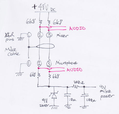
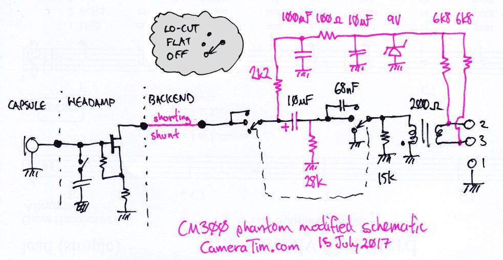
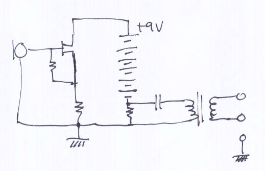
The 48 volt supply is inside the mixer, mike pre-amp, or mike power supply, and connects to both legs of a balanced audio line through a pair of resistors (6k8 Ω traditionally). The same voltage is applied to both legs of the balanced line, the ground wire forms the other half of the power circuit (see the schematic, below). At the mike end, another pair of resistors will connect to the power circuitry inside the mike (again, traditionally they'll be 6k8 Ω on each leg of the balanced line). By this stage, the voltage has dropped significantly, by virtue of going through several resistors, and whatever voltage regulation components are in the mike. Phantom power starts out as 48 volts inside the mixer, ends up around half that voltage at the XLR connectors between the mixer and mike, and is much less in the power circuit within the mike.
The resistive coupling allows a degree of isolation between the power supply and the audio signal, so that the power supply doesn't short out the audio signal, and any wiring shorts shouldn't be a problem to the power supply. Applying the same voltage to both legs of a balanced circuit means that there's zero DC voltage across them. Or, to put in another way, there's no difference between each leg. This means that you don't fry audio transformers, or mike voice coils (unless you have a very old mike with a grounded centre-tap, and those kinds of mikes should not be connected to phantom power circuits, or must be modified before doing so).
Some cheap modern mixers don't supply 48 volt phantom power, only offering lesser amounts. While it's possible this mod may work with a mixer supplying a lowly 24 volts, it's highly unlikely that it will work on anything less. While you could change the resistors to work with a lower supply, you stand the risk of killing the mike if you ever connected it to a normal 48 volt phantom supply (you'd need to work out the power handling capabilities of your zener diode, to see if it will protect the mike, or be destroyed).
NB: Other methods of sending power up the mike cable (T-power, A-B power, plug-in-power, mike bias, etc) are not “phantom power,” and not compatible with this modification. The correct use of the title “phantom power“ only refers to the technique I've outlined above. If you use the wrong type of power system for a mike, you're very likely to damage or destroy the mike.
The above sketch was just a quick drawing; I didn't intentially draw different chassis and ground symbols, they should all be the same symbol, they are all joined together. The use of phantom power in a mixer does mean that the ground pin of the XLR has to connect to the mixer's DC power supply ground, too, so the audio connections can never be completely unreferenced to ground (unlike in a transformed-coupled input with a dynamic mike, where input stages can be completely isolated from ground). Potentially, this can be a cause of electrical noise. And is yet another reason why some people don't like using phantom power systems.
Why I'm modifying them
I bought my Nakamichi microphones well over twenty years ago, and have kept using them because I'm happy with them. However, they can only be powered by a 9 volt battery, ones that were expensive when I could still get them, and are no-longer available. So I made my own batteries up by taping six LR44 button cells together into a battery, and packing them in a cardboard surround, with a conductive spacer to make them the same length as the original batteries were. This was actually a lot cheaper than the original batteries, by at least 50%.
While cumbersome to have to do, my recording equipment didn't have a phantom power supply, and the mikes couldn't use one, anyway, so I put up with the inconvenience for a very long time. When I bought them, as brand new equipment, back in the 1990s, I was told there was a phantom powered backend available, but never followed that up. I was aware that there is an inferior CM100 backend that uses 1.5 volt batteries.
For those of us who have used low-voltage powered electret microphones, we've noticed two things. The higher the battery voltage (within the capability of the mike), the better the mike handles extreme sound levels, the quieter its noise floor, and the longer it carries on working while the battery runs down.
NB: If you try putting 1.5 volt batteries in the CM300, it gives a woeful response. The sound is very muffled (lacking in treble, and overall signal strength). The CM100 and CM300 backends have supposedly have different internal circuitry (though not significantly, from what I can see on their schematics). But the CM300 definitely starts to produce bad audio as the battery power drops down to around 7 volts.
To be honest, I'm not a fan of phantom powering, but it is a useful feature. What I specifically don't like is the horrendous noises produced when connecting and disconnecting leads, when moving cables that don't have very good connections (some combinations of particular plugs and sockets never seem to fit together very well), when switching mikes on and off, the hums that can be created by bad phantom supplies in mixers, and mixers that only have one master switch for phantom power to all XLR sockets can be a complete pain when you have other things connected to the XLR sockets that cannot handle phantom power being applied to them. Not to mention the ability to destroy mikes when there's a short in a cable, or a failure in any of the four 6k8 Ω resistors used in the phantom power circuit (see the phantom power schematic, above). It's essential that both legs of the balanced audio line have exactly the DC same voltage on them, else you fry components that are only designed to work with miniscule AC voltages (phantom power is around 48 volts, microphone signal levels may be few milli-volts, that's around a thousand times less).
NB: Those concerns relate to any use of phantom power, with any mixer, and any microphone. There's nothing special about this mod that makes this mike more vulnerable, nor more robust, than any other mike.
Having said that, since all my current recording equipment can supply phantom power, and getting sick of the nuisance of batteries, I decided to bite the bullet and modify the microphones to run off phantom power. Technically, it's not hard to do. It's just an awkward thing to do, mechanically (disasembling the mike without damage, and fitting everything into a tiny space).
After modification, the mike can still be battery powered, but you need to switch off any phantom power (from your mixer or preamp) before doing so. This modification leaves everything else as it was before: The switch works in the usual way, you can swap capsules and heads. The audio characteristics should be the same as they always were. Mine sound unchanged. I modified them one by one, and compared each mike, with the others, as I went along.
How to use these modified mikes
This modification is make these mikes be useable like any other phantom powered mike, on a mixer with the traditional +48 volt phantom power supply. You won't need special interfaces, special cables, special anything. i.e. This mike, connected by a standard XLR cable, straight into the microphone input on an audio mixer.
For phantom powering, remove the battery, and install the shorting shunt where the battery normally goes. Then use the mike in just the same way as any other phantom powered mike. (The shorting shunt connects the mike's two battery terminals directly together, passing power into the headamp, and the audio signal down through the backend. It's simply an insulated conductor the same size as the original battery.)
For battery powered use, remove the shunt, install the battery, and ensure that no phantom power is being supplied to the mike. Use the mike in the same way as any battery powered mike.
For either powering method, the off/flat/lo-cut switch works exactly as it's labelled, switching the mike off, switched-on with flat equalisation, and switched-on with low-cut filtering. Switching it off mutes the mike, and disconnects the power (battery or phantom), you do not have to remove the battery to stop it going flat.
Disassembly
It should go without saying, but keep your fingers off the electrical contacts. The oils from your skin, and whatever muck you have on your fingers, can eat into the metals and make the contacts unreliable.
Remove the head, and take out the battery. Leave the head off.
Carefully prise off the switch label (it's a thin metal plate held on with a little bit of glue). If you're careful, you won't bend it, and you can easily glue it back on in a tidy fashion. All of my mikes only had a tiny dab of glue at each end of the metal plate.
Remove the three black screws in the mike body close to the switch assembly.
Carefully pull out the XLR and switch section, together. It may help to poke something into the battery compartment, and push the end off at the same time as slowly pulling it apart. There's three fine wires between the XLR section and the switch section, with very little slack. If you yank out the XLR section you'll rip the wires off. As you slide this out of the main barrel, a grounding tag will pop into one of the screw holes above the switch assembly, poke it back into the barrel, through the screw hole. This entire section will come out, the barrel is just a hollow tube.
Carefully unsolder the battery spring from the top of the circuit board.
Remove the two silver screws in the switch, and carefully extract the circuit board.
Note where the XLR connector wires go so you can re-attach them when you accidentally break them off (it's virtually unavoidable). Alternatively, desolder them now, to make handling easier. If you want, you could replace them with slightly longer wiring, to make re-assembly a bit easier. In my opinion, the two audio lines should be twisted around each other for extra noise rejection. The ground wire should be separate. I see no point in using shielded wiring, here, as everything is inside a grounded metal tube.
NB: My mikes had the red wire going to the pole on the transformer nearest to the battery spring, and XLR pin 3. The white wire going to the other pole of the transformer, and XLR pin 2. And the black wire going to the ground below the switch. This use of the red and white wires is the other way around than usual, but they are wired with the correct polarity.
I have tested, and confirmed, that the mike is wired up to the expected norm (positive pressure against the mike element produces positive voltage on pin 2, relative to pin 3). While this doesn't really matter with single-mike recording, it does for multi-miking. When multi-miking, all mikes should have the same polarity, as a general rule. So wire all your mikes the same way. If you had to reverse-phase a mike to deal with an acoustic problem, you'd do so by switching polarity at the mixer, or inserting a reversal dongle in the mike cabling (for those mixers without a phase reversal switch), but not by rewiring the mike.
Assembly is virtually the reverse process. Though be sure that your extra components aren't getting crushed or shorted out, as you go along (remember, the barrel is grounded). You may want to add some insulation between the board and the barrel. I trapped some cardboard in there, so it's easily removeable, and there's no sticky tape goo to deal with.
If you're glueing the switch label back on, you only need a couple of dots of contact glue at each end (the same as it was originally fixed into place). If you ever have to disassemble the mike again, you don't want it to be harder to disassemble than the first time around.
Modifications and diagrams
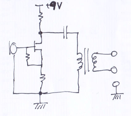
There are some variations (component arrangements and values) between the supplied diagram (in the manual) and what's in my mike. Whether all mikes are different, or the design was changed mid-production, I'll never know, but the basics are similar enough to detail a general mod that ought to be possible to do on all their mikes.
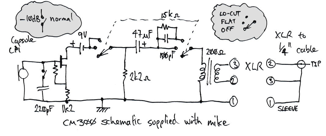
The DC-blocking cap is a different value (10 μF instead of 47 μF), and only 10 volt rated (yet another reason not to use more voltage than the specs say to use). The other capacitors are different values, too, and the resistor in the headamp in series with the FET. The resistor on the FET's gate is unidentified on their diagram, and neither is the FET.
Quite what the 15 kΩ resistor is useful for (where it actually is) eludes me, since I expect the transformer that it's in parallel with will be a lower impedance than the resistance. I reckon that the low-cut filter is going to be formed more from the 68 nF cap and transformer combination, than the cap and the resistor.
The mike-muting part of the power switch circuit actually grounds out the output transformer, rather than leaving it open circuit.
The head-amp attentuator switch works by shunting the output of electret element and input of the FET pre-amp with a small value capacitor to ground (it reduces the signal level by 10 dB). The supplied schematic has a slightly higher value capacitor than I found in my mike, but this difference probably isn't terribly significant.
They inverted the output from the transformer on their diagram (the XLR pins 2 & 3 are labelled the wrong way around on the mike output), but the XLR to ¼″ cable diagram is correct (with pin 2 to tip, and pins 1 & 3 to the sleeve). And, in reality, the mike exhibits the standard behaviour that positive pressure against the capsule produces positive voltage on XLR pin 2 relative to pin 3 (and positive on the tip relative to the sleeve).
Despite what their diagram suggests, there isn't a singular ground path through the entire circuit. The mike is formed out of three sections (capsule, headamp, and backend) that screw together, and each section has its own complete circuit. Each section is joined together by a single pole (where I've drawn the very fat dots for the capsule contact, and the battery contacts), and the ground path between them being made via the chassis. My schematics just show all the grounds as a connection to chassis, to make it easier to draw the diagram.

NB: Anywhere these modification instructions mention 9 volt DC supplies, it refers to the modifications for the CM-300 mike. When involved with doing the same modifications to a CM-100 mike, it will actually be 1.5 volts. While the CM-100 may have a slightly different headamp, filter, and mute switch arrangement, the modifications are done around the power switch section, and that's the same in both mikes.
-
Remove the earthy end of the 2k2 Ω resistor, this will be connected to your filtered low-voltage supply, instead of the ground. The other side of the resistor is the tap-off point for mike audio from the power supply circuit current.
 Disconnected ground end of 2k2 Ω resistor
 -
Remove the 47 μF (or 10 μF) tantulum capacitor, and replace it with a non-polarised capacitor of the same value. But if you never intend to use battery power again, you can put the same capacitor back in, with the opposite polarity to its original installation (the bias across it is a different polarity for phantom power than when battery powered).
It can be hard to find a small non-polarised 47 μF cap, and a lesser capacitance value will suffice (look how small the low-cut filter's capacitor has to be, 68 nF, to make a significant reduction in the bass response). And in my mikes, the actual component was a 10 volt 10 μF (so it doesn't need to be 47 μF, which seemed a bit excessive, to me; and is yet another reason not to use a supply voltage above the original design). 47 μF does work fine, I know that because I believed the diagram, and bought that value component before I opened up the mike, installed it, then replaced it with 10 μF, later on (a smaller cap may reduce the turn-on thump, a bit). To fit a large cap into the place of the original tantulum, the 68 nF cap may need to be removed and re-attached on the track-side of the PCB.
-
Add two 6k8 Ω resistors to XLR pins 2 & 3 leading into your phantom power filter circuit. These two resistors should be extremely well matched in value, use 1% tolerance resistors. For best results, use an accurate meter and find the two closest matching resistors that you can.
-
Add a 9 volt zener diode across the phantom power input to ground for the CM-300 mike, use a 1.5 volt zener for the CM-100 mike. The current is quite small, so you won't need a special zener.
-
Add a 10 μF capacitor across the phantom power input to ground.
-
Connect a 100 Ω resistor between the phantom power input and the free end of the 2k2 Ω resistor.
-
Connect a 100 μF capacitor from the junction of the 100 Ω and 2k2 Ω resistors to ground. This junction is now the filtered low-voltage DC output from the phantom supply.
NB: The 100 Ω resistor and 100 μF capacitor are mainly there to remove the noise created by the zener diode (which sounds like a rather significant amount of amplifier hiss), the phantom supply from the mixer should be quiet, to begin with. And the 100 Ω resistor before the 100 μF should limit its initial charge-up current, a bit.
The alternatives to using a zener are a low-power voltage regulator (which could be a noise source, as well), or just using a resistive voltage divider (which would produce the wrong voltages if you plugged the mike into another mixer which had different resistor values in its phantom supply, and/or a different supply voltage). So I feel the zener diode and filtering components are the simplest robust solution (and they're a tried-and-tested traditional way of doing power regulation in phantom powered mikes).
-
Add a 28 kΩ resistor between the 47 μF (10 μF) capacitor and the low-cut filter switch, to ground, if you don't like the noisy pop as the mike is switched on and off, or as the low-cut filter is switched in and out. That will keep the charge across the cap (virtually) the same all of the time. The resistor value was picked so it shouldn't significantly change signal levels or frequency response. It reduces the switch-on pop a bit, the switch-off pop quite a lot, and virtually eliminates the pop when switching the low-cut filter in and out.
A turn on pop is unavoidable, unless you short out the first half of the switch, and always supply power to the mike head, keeping the second half of the switch that disconnects the audio output transformer (and switches the low-cut filter into circuit). Bearing in mind that, if you do this, you should always disconnect the XLR before unscrewing the head of the mike or changing capsules. And you'd have no way to switch off when using battery power. For those reasons, I feel that adding the capacitor drain resistor is the better approach.
Most of these components can all be squeezed into the space between the switch and the transformer (which, I have to admit, doesn't look a stunning quality transformer, but I've never had cause to complain about the sound quality from my mikes, balanced audio provides many benefits, removing it is likely to cause all sorts of problems with the mike circuit, and it'd be hard to replace such a tiny transformer with a different one). A few of the components will need to be mounted on the track-side of the PCB.
If you're going to continue to battery power the mike, and you're using batteries that are smaller than the originals, now would be the time to replace the spring terminal with a longer one (or put a permanent spacer in, and move the existing spring closer up the barrel). If you're replacing the spring, you can make a custom one by coiling up a paper clip. Insert an insulating collar around it, so it can't bend over and touch the shell of the mike (the shell is audio ground, and the battery negative pole is different from ground).
Test the circuit before reassembly. Connect the backend (without a head) to a mike preamp with 48 volt phantom power. Switch the mike on. There will be up to +48 volts DC on pins 2 & 3 of the XLR, against ground (the backend will load it down, somewhat). On the other end of the two 6k8 Ω resistors will be +9 volts DC against ground. If the zener was not there, the voltage supplied to the mike would need to be reduced in some other manner (such as a voltage divider), but the voltage could vary from one mixer to the next (if they have a different phantom supply feed resistance). The zener is a crude regulator, so that the mike gets a consistent supply voltage despite any variations in supply and load resistances. There should be +9 volts DC between ground and the spring battery terminal, positive voltage at the spring terminal. And your mike input should be nearly silent, though you can make it buzz if you touch the battery spring.
Unplug the XLR lead, and reassemble the backend, but leave the head unscrewed. Reconnect the XLR lead, and test again that there's +9 volts DC on the spring terminal.
NB: As mentioned further above, when modifying the CM100 mike instead of the CM300, the low-voltage DC readings will be +1.5 volts, not +9 volts.
Insert a shorting shunt where the battery would go, this connects the spring terminal to the stud on the rear end of the mike head, passing power up from the phantom circuit into the head, and completing the audio path (which is a tap off from the power circuit's current loop). You could use a bolt wrapped in insulation (e.g. inside a cardboard tube). I used to back-to-back banana terminal sockets, with a spacer in between them (this allowed me to make the shunt the exact same length as the original battery). Make sure that your shunt can't rattle (the mike will pick up the noise, and you could short out the power into the metalwork of the mike body), and that it's a reliable conductor. Screw the head on. It's ready to go.
Although you could hardwire the two sections, this would make it difficult to unscrew without breakage, if you ever needed to work on the mike again. And make it very hard to swap heads. While the omni and uni capsules unscrew separately from the head, the shotgun capsules replace the entire head assembly. The point of this modification is to add a feature, not to take others away.
Things to bear in mind
It should go without saying, but keep your fingers off the electrical contacts. The oils from your skin, and whatever muck you have on your fingers, can eat into the metals and make the contacts unreliable.
The modification is for running the mike off traditonal 48 volt phantom power, it may work on modern el-cheapo 24 volt phantom, but probably will not run off even lower voltages. It's not suited for running off very low voltage mike-power, as found on 3.5 mm mike sockets on computers and domestic camcorders. Not only will that not work (it's an entirely different method of running voltage up the wire, as well as being a different voltage), you're likely to damage the mike. Phantom power is applied equally to both legs of a balanced audio line, mike power is applied to unbalanced audio lines, either on top of the audio, or up a separate wire.
Repeating the warning stated near the top of the page, you can power the mike by battery or phantom power, but do not try both together. You risk damaging the mike with excessive voltage, and risk destructive damage of the battery. Unfortunately, due to the construction of the mike (where the parts are located, either side of the battery compartment), it's very difficult to put in extra components to protect against this issue. Remove the battery, and replace it with the shunt, if using phantom power. And ensure there is no phantom power being supplied to the mike if you're using battery power. For what it's worth, some mikes that were originally built to be phantom or battery powered come with the same warning from their manufacturer (only ever have one kind of supply in use at a time), and for the same reasons.
Because there's, now, a zener diode in series with the battery, the battery voltage to the head will be slightly reduced. This may affect how long the mike continues to work effectively as the battery runs down, though I don't expect it to be a significant problem.
If you are going to use batteries, you should not use mixed types, all cells that make up a battery should be exactly the same as each other in all of their parameters (voltage, chemistry, etc). You you shouldn't even mix new and flat batteries. When you don't observe these rules, at some point as the batteries discharge (each at different rates), some of the cells may have reverse polarity put through them, and cause damage. Chemically speaking, batteries are quite powerful little things, and can be surprisingly destructive. So put six 1.5 volt cells together, or three 3 volt cells together, or two 6 volt cells (and risk 12 volts going through the mike), but don't stack a 3 volt and 6 volt battery (it's highly likely that they will not be matched, unless they were both constructed using exactly the same kind of individual cells in each, such as both batteries being made out of groups of LR44 button cells packed together).
Although I've seen people say these mikes can withstand more than 9 volts going through them, mine had a 10 volt tantulum in it, and exceeding the working voltages of capacitors can be very destructive. I have no specs for the components in the headamp, so have no data to suggest that putting higher voltages through it will be okay. Also consider that since the mike specs say use 7 to 10 volts, and the actual mike components often differ from the schematic, you can expect that some mikes may have different components from others, so long as they adhere to the mike's general specifications. So I simply wouldn't risk over-powering the mike.
The components that will determine the maximum supply voltage that the mike can handle will be: The electrolytic or tantalum capacitors (the 47 μF or 10 μF DC blocking capacitor, and the phantom supply filters), the FET in the headamp (which could be different than mine, so you'd need to investigate your mike's FET's specifications), and the capsule itself (for which I have no clues about its true specifications).
Do not use unbalanced audio leads to connect phantom powered mikes. Putting phantom power up an unbalanced lead will fry the mike's transformer. And, on the converse angle, when battery powering a modified mike, there is a chance of a small amount of battery current coming out of the mike into an input stage.
Things not to worry about
The original mike batteries ranged from 8.something to 9.6 volts, as fresh battery voltages (when I was using the original batteries), so you don't need exactly 9 volts. However, don't kill them with excessive voltage. I've read someone say they can survive 12 volts, but I have no way to verify that, non-destructively. Stick to what they're designed for (the manual says 7 to 10 volts), and at least one of my mikes has a cap in it that's only rated for 10 volts.
Some modders suggest bypassing the switch, I'd say leave it as is. If you're using multiple mikes, being able to mute individuals to work out which one is plugged in where is handy. It's convenient to mute mikes that are about to pick up a lot of handling noise as you adjust things. And the low-cut switch is still useful to have. Though, if your switch has gone unreliable, and you can't fit a replacement, by all means bypass it.
Some modders suggest removing the transformer to increase the output. I'd advise against that. You're removing the benefit of balanced audio lines, you're upsetting the impedance the headamp is designed for, and most mixers have enough gain that you don't need to even consider boosting the mike output (by some insignificant amount). And, if removing the transformer inverts the output voltage, you've no way to correct it.
I wouldn't bother replacing caps with exotic varieties. These are old mikes, they're not multi-thousand dollar high-end mikes. Your cabling and mixer input stages are going to have far more effect than the unmeasurable difference resulting from changing a capacitor that had nothing wrong with it. Having said that, bad tantulums are known to go noisy or short circuit, so if you encounter that type of problem, replace it.
Likewise, regarding changing resistors for special types, or other mods to try and change the audible characteristics of the mike. The changes will be miniscule, or random without any real quality control, nor accuracy. The manufacturer designed the mikes well in the first place, and boosting parts of a frequency response only gives the illusion of better sound (the mind is fooled into liking louder or brighter sound, but that doesn't mean it's actually an improvement). That midrange boost in some mikes, plus the midrange boost in some speaker systems, can soon become a nasty peakiness that sounds nothing like the original audio. But if you want a different sound out of a mike, use the equalisation controls on your mixer or computer, instead of bastardising a mike.
You may have gathered, by the above notes, that I'm one of those people who hate the nasty audio that sound re-inforcement guys often create when they mike-up singers and acoustic instruments (removing deep, or even mid-bass, making mid-range shrill, removing the harmonics of instruments, etc). They should switch off their gear, put their head where a conductor would stand (or another player, or sit in the audience), and listen to how the audio actually sounds like, then try to recreate that.
For your battery powered CM300s (whether you've modified them, or if they're still in the original condition), the power switch does completely isolate the battery, they will not drain flat while inside a switched-off mike. Though, you may still want to remove batteries when storing mikes for a long time, to avoid leakage. But if you're using them semi-regularly, you'll notice the battery going flat long before they might leak. And avoiding unscrewing the mikes (any more than you need to) preserves the lifespan of the thread.
When battery powering mikes, leave the mike on for your whole recording session. Don't switch it on and off trying to save a few minutes of battery life. Firstly, you're highly likely to accidentally leave a mike switched off at an inopportune moment. And switches have a finite lifespan, so switching it on and off ten times more than is needed reduces its lifespan by a factor of ten. Then you have the fun and games of using a mike with an unreliable switch, or having to pull the thing apart to try and replace it (probably with one that's not quite the right size, too).
The original Nakamichi mike manual had some confusing text advocating using unbalanced inputs over balanced inputs, for if you didn't need to use balanced audio. If, for instance, you weren't in an electrically noisy environment, or weren't using very long microphone cabling, then the advantages of using a balanced-audio connection aren't as significant. The reasoning behind their advice was that some balanced input stages use an input transformer, but most unbalanced input stages do not, and it may be better to avoid going through another transformer. However, you don't usually have a choice of types of input stages on most equipment, connecting an unbalanced line to a transformer still passes all the audio through that transformer, most modern equipment no-longer use transformer-coupling in their balanced-audio input stages, many situations do benefit from the advantages of using balanced audio connections, transformer-coupling often has significant electrical-interference noise-reduction benefits, good input transformers do not significantly colour the sound, and you're probably going to play with the mixer's tone controls, anyway. Well, in over thirty years of productions, I'm yet to see anyone leave their mixer's eq controls set neutrally on their mike channels. And that's going to have a far greater effect than what any input transformer will do. So, I say, use the normal XLR balanced audio cables for all your mike connections, all the time. They're a lot more convenient and reliable than tip & sleeve phone jacks, especially when you need to extend a lead.
When patching and unpatching phantom powered leads, they can make extremely loud noises through your audio system. When doing so, mute the mike input channel, mute any pre-fader sends, mute your monitors, take your headphones off, etc (do whatever's practical and convenient without being paranoid about it). Some mixer manuals advocate that the phantom power, or the entire mixer, should be switched off during patching, but that seems to be taking things a bit too far, not to mention that some input sockets may still have 48 volts on their output for a minute or more after being switched off. Broadcast studios have permanent phantom power on their patchbays, and have equipment that survives, unscathed, while being patched in and out for donkey's years. And I see no reason why this microphone circuit (whether modified for phantom power, or not) would suffer if you plug in, or unplug it, while phantom power is switched on. Just do what's needed so nobody has to hear the horrible noises while you play with patch leads.
General info for those who don't have a manual for CM300 or CM100
The off-switch does completely disconnect the battery (whether you've modified your mike, or left it in the original condition). You don't need to take batteries out to prevent them going prematurely flat. Though you might want to take them out if you won't be using the mikes for a long time, to avoid battery leakage damage. The positive end of the battery faces the capsule end of the mike. The operating voltage of the CM300 mike is 7 to 10 volts, and you could expect around 220 hours of battery life with the original batteries (which are not made anymore). The CM100 used 1.5 volt AA batteries, and you could expect 200 to 500 hours of battery life (dependent on the particular battery that you're using).
The “low-cut” switch reduces the bass response (−10 dB at 100 Hz), this compensates for the over-emphasised-bass proximity-effect when close-miking with a cardioid capsule, and can reduce the rumble caused by blowing wind, and low-frequency resonances in some rooms. Otherwise, the “flat” middle switch position is the normal operating mode. The low-cut filter is after the pre-amp, and presents no advantage over doing low-cut filtering at the mixer, instead. In fact, doing low-cut filtering at the mixer gives you much more control over the tonal quality of the sound. Speaking in general, I've come across too many situations where a simple low-cut filter completely ruins the sound quality, by excessively attenuating bass frequences. And the amount of bass-cut needed to counter the proximity effect will be determined by the distance between the mike and the sound source, a simple on/off switch can't cover all those variations. Though, it's still useful to have for those cases where low frequency sound is causing problems, and your other equipment has no low-cut filtering.
There's a −10 dB attenuator pad inside the headamp for the CP1, CP2, and CP3 capsules (unscrew the capsule for access), for dealing with very loud sound levels (the CP4 capsule has a built-in headamp, with no attenuator control). As the attenuator is on the input of the headamp, it can prevent overload within the microphone. In some situations you will need to use this attenuator (it's no good trying to reduce the gain of equipment you've connected the mike to, if the mike is being internally overdriven). Take care when rotating the attenuator switch, it can jam, and do not scrape off the contacts. Keep your fingers off the contacts, use a tool to rotate the switch.
Switch off before dissembling any part of the mike. Be careful not to cross-thread or over-tighten.
The mike capsules are rigidly mounted with no anti-shock suspension. The mikes are intended to be mounted, not hand-held, and have no isolation against handling noise, nor from sound transmitted through the mount. If you have a shock mount, be sure that there is a loose loop of cable between mike mount and cable clamp, so that the cable doesn't transfer sound from the stand (or floor) into the mike.
| CP-1 (cardioid) | CP-2 (omni) | CP-3 (super omni) | CP-4 (super directional) | |
|---|---|---|---|---|
| Frequency response | 30–18,000 Hz ± 3.5 dB |
20–16,000 Hz ± 3.5 dB |
20–18,000 Hz ± 3.5 dB |
30–20,000 Hz ± 3.5 dB |
| Output impedance (1 kHz) | 200 Ω balanced ±20% | |||
| Sensitivity (1 kHz 0 dB = 1 V/μ bar) |
−76 dB ± 2.5 dB | −74 dB ± 2.5 dB | −76 dB ± 2.5 dB | |
| Signal to Noise Ratio (weighted) | > 50 dB | > 46 dB | > 50 dB | |
| Maximum SPL at 3% distortion CM-300 CM-100 |
138 dB 118 dB |
138 dB 120 dB |
118 dB 118 dB |
|
| Dynamic range CM-300 CM-100 |
> 114 dB > 94 dB |
> 107 dB > 92 dB |
> 94 dB > 94 dB |
|
| Current consumption | < 1 mA | < 0.5 mA | ||
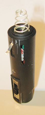
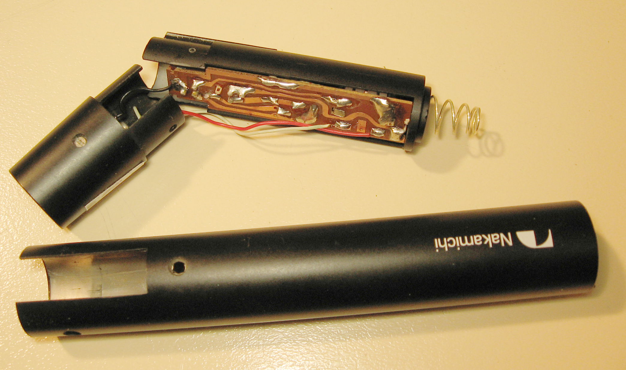
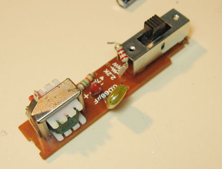
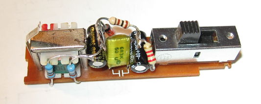
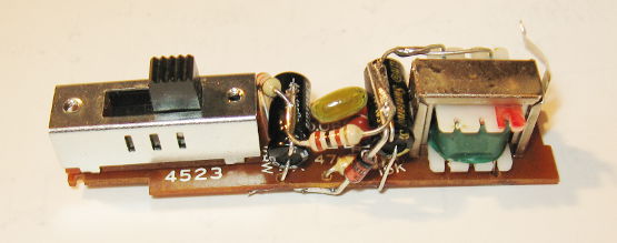
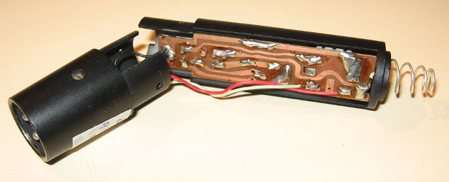
Innard photos
Linking to this page
If you have a page providing information about these mikes, or are answering someone else's queries, feel free to link to this page. I intend this page address to be permanent, though its content may update from time to time.
Written by Tim Seifert on 23 June 2017, and last updated 27 July 2021.