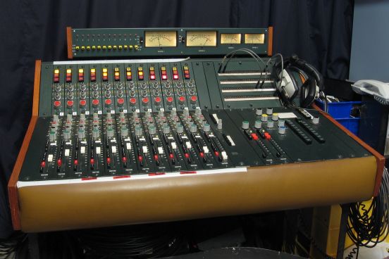
On this page are links to 300 dpi images scanned from the handbook for the Astor Audio Mixer. It is the entirety of the manual, plus some of my own notes made many years ago (as extra sheets at the very end). Each small preview image is a link to the full-sized version (which are around 1 meg on average). Alternatively, you can download a 141 meg PDF of the Astor mixer handbook compiled from all these image files.
Various diagrams went off the edge of page in the original handbook, and some aspects of the mixer are not detailed in the manual. All the images, here, are as complete as the ones in the book. Where a diagram was on larger than an A4 page, I have scanned the page in A4-sized chunks, and stitched the images together. There are gaps in some of the file numbers, simply because some pages took a few attempts to scan them acceptably, and I have discarded the bad ones.
The pages were not white, but various shades of buff, and I have not compensated for this (so some pages are darker than others). Other than three pages which had coloured material, all the (other) scans are reduced to monochrome images.
Save any files you want to keep, as they may not be permanently stored on this website. If you want less compressed files for better printing quality (approx 1.4 gigs worth of image files) , or a very large PDF file of the whole lot (approx 890 megs), I can send them to you on a DVD or USB flashdrive, in the post, but you will have to pay the costs of blank media and postage.
Points of interest on this page
- Section 1 - Table of contents
- General information
- Installation and setting-up
- Operating notes
- Technical data
- Parts list
- Console layout
- Connectors & plug-in cards layout diagram
- Overall block diagram
- DC switching and signalling schematic
- Module remover tool diagram
- VU meter pad board layout
- Monitor switch panel layout
- Monitor switch panel schematic
- Section 2 - Input channels
- Section 3 - Input channels' output switching router
- Section 6 - Master module
- Section 9 - Talkback module
- Section 11 - Power supply
- Section 12 - J & K amplifiers card
- Section 14 twin J amplifiers card
- Section 17 - Equaliser
- Section 18 - J amplifier
- Section 19 - K amplifier
- Section 20 - M amplifier
- Section 22 - Power regulators
- Section 23 - Low cut filters
- Section 30 - Oscillator
- Resistor data table
- Appendix A - Suppliers
- Appendix B - Connectors
- Reverb return module block diagram
- Channel output routing notes
Scans


Other notes
The mixer is mostly working, with a few niggles. There's one input channel out of action that needs some transistors replacing, a few other channels that need transistors replacing (but are still working without them), then it's just the usual things—scratchy pots and switches, and some capacitors that need replacing.
The buffer amplifiers for things like the group outputs, reverb sends, pre-fade listen, and the oscillator, are on plug in cards mounted inside the console, with their output transformers mounted nearby on the main chassis. The reverb send amplifier, and pre-fade listen, cards have level controls inserted between their input and output buffers that are cabled up to the monitor panel.
There are no sections of the handbook dedicated to the reverb send, and pre-fade listen, amplifiers. You're expected to read the overall block diagram to see how generic amplifier modules are being used in several places.
The monitor switch panel directly feeds the main VU meters, and the studio and control booth sends, without using any buffer amplifiers. Operation of the switches, level controls, and the equipment connected to their output feeds can affect the main mixer output.
The headphone feed used to be unbuffered (two completely separate balanced lines to medium impedance headphones, for left and right), but a small buffer amplifier was installed below the monitor panel (for normal, modern, unbalanced headphones with a common ground). There is no information for this module, and it was not part of the original design. It's a basic headphone amp circuit on veroboard.
The pre-fade listen buttons tap into the input channels before the channel pad and faders, and the PFL amp has a separate gain control, making the PFL useless for setting up levels. It can only be used for listening to the audio.
The over-press switch at the infinity position on the Penny and Giles faders isn't wired up to do anything (other mixers, often, use that as a PFL switch).
The monitor muting logic automatically turns off the studio monitor feed when there's a microphone channel routed through to one of the buses, and the faders are raised from the infinity click-stop position. But is not affected/controlled by the channel mute buttons (pressing the channel mute switch will not switch the studio monitor feed back on).
The channel mute switches are quite unreliable, and some of the other buttons on the input channels. They're mechanical push-on/push-off buttons that connect, disconnect, and reconnect, while they're being pushed (e.g. when you push the mute button, the channel mutes, loses the mute, then remutes, with scratches and crackles). I suspect that it's not just dirty contacts, but that the slider moves completely past the contacts, then comes back again. The original design had DPDT mute switches grounding both sides of a balanced line leading to the balanced fader pot, the boards had been modified so that they simply shorted the balanced line out against itself, and not to ground (as per the schematic in the handbook). Presumbably there was a capacitor discharge pop when grounding the lines.
The talkback module will mute the control booth monitors when the ident buttons are pressed (for recording an ident from the control booth talkback microphone), and the talkback channel 1 or 2 buttons are pressed (talkback channel 3 is a completely independent feed). And it will switch over the studio monitor feed to the talkback output when the talkback channel 1 or 2 buttons are pressed. Talkback and ident buttons need disengaging for normal mixing and monitoring operations.
Power to the channel alive indicator lights, and the various logic control switching was disconnected (muting, etc.). The switching of 50 volts on and off introduced pops and clicks into the audio, and an increasing hum can be heard as more panel lights are illuminated. The hum probably can probably be reduced by replacing the main power supply filter caps.
Most of the channel output routing switches (to group 1, 2, and master stereo busses), and the monitor switcher, had blown indicator lamps. The cost to replace them was beyond belief (around 50 lamps at a few dollars each), so they've been progressively replaced with LEDs. The blown lamps were a push-in affair on a wedge base with terminals either side, so the glass was crushed out, and a LED and dropping resistor soldered onto the old base.
The mixer does not supply phantom power, though it wouldn't be too hard to add the feature (the “PH” switch on the input modules is a 180° signal phase inverter). Each module is supplied with an unregulated 50 volt DC supply, and each module has an on-board regulator to supply itself with 40 volts DC. A second 48 volt regulator could be fitted that could feed phantom power to the microphone cable. Although this could be applied to the input transformer centre tap, that would put a high DC voltage through the attenuator switch, and also to the line input socket. A better solution would be to AC couple the microphone line to the module, then feed the phantom DC power to the microphone line through a couple of resistors. It might be necessary to use slightly less than 48 volts, so that the regulator has working room if the main supply drops below 50 volts, else you'd get bad ripple current.
The mixer appears to have had the back panel replaced. It's a plain aluminium sheet; many of the mixer's connections are not carried through to the back panel, but are loose wires dangling below; the line inputs went to ordinary ¼″ jack sockets and were wired with tip and ring swapped around (likewise for the microphones inputs and line outputs); all the ¼″ sockets were uninsulated, so they connected the cable shielding to the chassis at the back panel and the central bus. Over time, I'd modified the back panel to: Swap all ¼″ sockets for insulated ones, and connecting each cable shield only to the jack sleeve, and not to the chassis at the jack. Shields are only grounded at the central bus. XLRs have the cable shield only going to pin 1. Add more ¼″ sockets to connect all the possible output signals through to the rear panel (all monitor outputs, talkback 3, PFL, oscillator). The external 19″ rackmount power supply was hardwired, now it's connected via two multipin XLRs (there's two supplies, as a dual-redundant parallel supply setup).
The underneath of the chassis is exposed. The bus wiring is unenclosed, and the rear section of the chassis is open. There are unused threaded screw sockets suggesting that there may have been shield panels, originally. This would seem like a good idea, for minimising noise ingress to the mixer, and to protect the electronics (the bus wiring extends below the level of the main chassis, and the desk has to sit on an open frame base, else the wiring and bus multipin connectors will be crushed).
Many of the pots are scratchy, and some were very unreliable (even after grinding the knob around, they don't clear up). The reverb send masters and the master channel gains have been replaced. Unfortunately, it's next to impossible to get anti-log pots, so the master gain pots are wired backwards.
The oscillator has failed, came to life once or twice, then failed again. The output transformer went open circuit. Resoldering its tags fixed it, once, then it failed further inside the transformer, and replacing it was the easiest option. The oscillator's line output buffer has two output terminals, one is DC coupled and the other is AC coupled. The old transformer was wired to the DC coupled output, for no apparently good reason, and this was probably its demise. The random replacement transformer was AC coupled, and works fine, tone generation-wise, but is low in output level. This is probably down to the wrong choice of transformer, than their being some other fault with the oscillator or its line driver amplifier.
Many of the illuminated mechanical switches are physically sticky and need lubricating. Several of them scrape against the chassis, as they're not mounted centrally within their apertures.
Some of the channel input modules have had a very peculiar repair done to them—they've completely removed two of the output transistors in their final stage J-amplifiers, and they still appear to work fine minus the transistors. It's one transistor from each side of the output circuitry, transistors 49 and 50 (on at least two of the input modules).
Some other details about this mixer are listed on the Astor equipment page in the business section of the website.