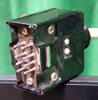
From the 1960s, these 8-pin rectangular connectors have been used to connect video monitors to VTRs. We've always known them as “Honda connectors,” presumably because Honda made the connectors used on these early machines. And some people refer to them as an EIAJ 8-pin video monitor connector.
They carry audio and video signals, in both directions: VTR playback to the monitor, and output from a TV tuner to the VTR (allowing recording of the station the TV monitor was tuned to, or from a stand-alone TV tuner).
Sony and Panasonic both used the wiring as shown on this page, yet Shibaden chose to use an incompatible scheme. And some 1980s computer RGB monitors choose to use this connector for their own purposes. If anybody needs these alternatives, and can't find them anywhere else, I'll have a dig through my old notes to find them.
They were commonly used with ½″ reel-to-reel VTRs, VHS editing VCRs, and Umatic VCRs, by Sony, Panasonic and JVC. All of the VCRs that I've seen used the same wiring, it was only the open-reel Shibaden that I've come across that wired it up differently.
The signal levels are usually the same as the individual video and audio input and outputs on the VTRs and monitors. I've never had any problems using a breakout cable between VTRs and monitors where only one of them had the Honda connector.
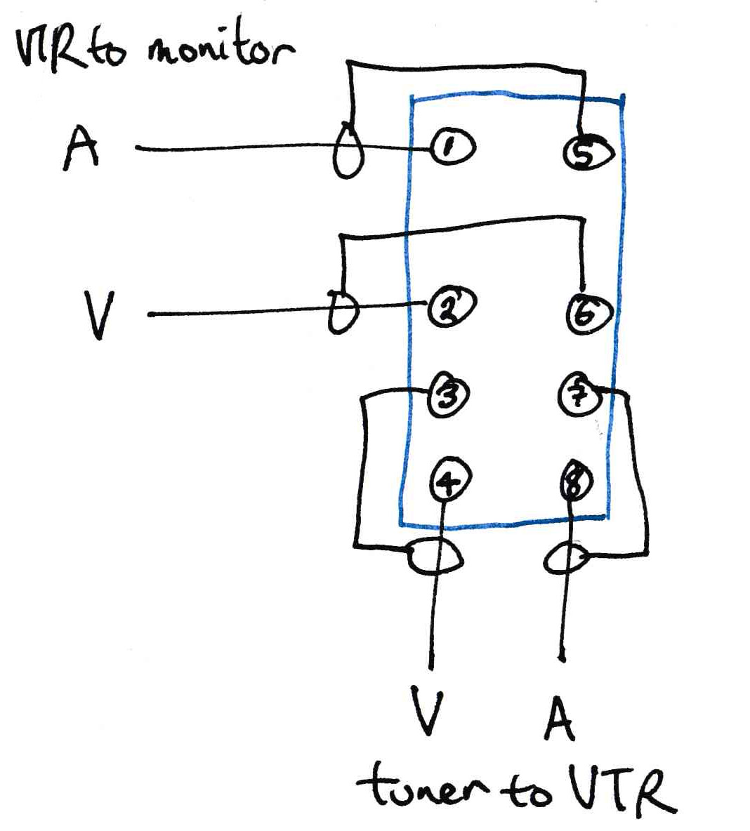
The cables use straight-through wiring, pin 1 goes to pin 1, pin 2 goes to pin 2, etc. So, for example, the VTR's video output on pin 2 goes to the monitor's video input on pin 2.
There are multiple ground pins on these connectors, each for their own purpose. Don't use the wrong ground, and don't join them together. Wire them up exactly the same as the adjacent wiring diagram.
Connector part numbers
Occasionally people want to buy one of these, looking through my 1991 Sony catalogue, some of the following product codes may help you track parts down:
Male 8-pin plug for VMC cable part 1-506-161-00 (I presume “VMC” means “video monitor connector” or “cable”). This is a complete plug, with backshell, nothing else.
Female 8-pin plug for VMC cable part 1-509-113-00. Again, this a complete socket with backshell, nothing else.
Premade 8-pin male to 8-pin male cables; VMC-3P (3 metres), VMC-5P (5 metres), VMC-10P (10 metres), VMC-25P (25 metres), VMC-50P (50 metres).
VMC-1H is an 8-pin female to 8-pin female connector block (used in between two male-to-male cables, to connect them together).
VMC-1N is a Y-lead with two male plugs and one female connector. It looks like it's intended to be used as a dubbing lead (audio & video out from a player VTR, going to the inputs on a recorder VTR, then a socket for you to connect a monitor cable to the recorder's outputs).
VMC-1M is an 8-pin male to a 10-pin male CCJ camera cable (commonly used to connect a monitor to a very old portapak VTR, so there will probably be a resistor between the tuner audio out and VTR audio in pins, as most of those VTRs had a microphone level input; or it may just rely on the tuner output being a high impedance going into a low impedance input stage).
VMC-1MQ is an 8-pin male to a 14-pin male CCQ, intended to connect a monitor or tuner to a U-matic portapak VCR.
Hirose also used to make the connectors, as part of their 1300 or 1600 8-way series. If you can find someone with parts, you'll need to compare images and measurements, because Hirose make all manner of multi-pin connectors with different shapes and sizes. One 1600 series plug I saw used square pins, which wouldn't fit into most Honda connectors (they use round pins). And I saw comments saying that the plugs were too big, use the 1300 series, instead (their various 8-pin plugs and sockets and backshells are their 1308 connectors).
Other RGB/RGBI/non-VTR uses
They were also used for a digital RGB signal connector on Dick Smith CAT computers (an Apple ][ clone). And some Japanese computers, apparently, using this pinout:
- Intensity
- Red
- Green
- Blue
- Ground
- Unused
- Horizontal sync
- Vertical sync
Another vintage Japanese computer (PCT-55) system apparently used them in this fashion, for digital RGB video:
- 14.318 MHz video clock (not connected–special purpose, not needed in general)
- ground
- digital bright-up (will only get 8 colours if not connected, 16 if used)
- horizontal sync
- vertical sync
- red video
- green video
- blue video
NB: I don't recall my source of the PCT-55 information (some two years ago) but it may be that they were listing the pin-outs of the computer, and the cable between the computer and the monitor isn't a straight cable where pin one goes to pin one, pin two to pin two, etc. An email I recently received indicates that's the case (an oddly wired cable), with the PCT-55 monitor connection being the same as the listing above this one, save for the clock signal on the (otherwise) unused pin 6, and the computer end going to a round DIN connector with the above pinouts. You'll have to do some experimenting, I can't tell if all those computers were the same.
Digital RGB would only give you 8 possible colours (white, yellow, cyan, green, magenta, red, and black), and yes I know white and black aren't “colours,” but all the literature refers to them that way. A slight improvement is RGBI, where they've added an intensity/bright-up signal. Ostensibly, this is to add a bright-up signal, allowing you to have 16 colours (each of the original possibilities, plus a brighter version of each). But practically, it works the other way around. The original colours are, now, dim versions (grey, dark yellow, dark cyan, dark green, dark magenta, dark red, dark blue, and black), and the bright-up signal is used to make them bright white, bright yellow, bright cyan, bright green, bright magenta, bright red, bright blue, and another grey (when the bright-up signal is switch on in tandem with the colour signals). Some monitors may even have a 8/16 colour mode switch, so that you can brighten an RGB-only signal to full intensity.
NB: I have no reliable data on what the scan rates are for these video signals. Your monitor will need to support whatever rate the video source uses. For some low-end systems (such as a system that could also be plugged into an ordinary television's composite video or RF inputs), this will usually be the same as NTSC scan rates, though the Amiga also supported PAL scan rates, other systems may have double the NTSC horizontal frequency (akin to VGA).
In 2021, I found out that the same plug was used on an Ibanez UE405 effects device for a remote control input. From the schematic pictures I saw, it is the same connector. But used in an entirely different way:
- compressor on/off
- phaser on/off
- distortion on/off
- flanger on/off
- total on/off (a bypass mode)
- +15 volt supply to foot switches
- ground
- not connected
The foot pedal unit has momentary contact switches that go to data latches, which will supply a steady on or off signal to the main unit (emulating mechanically latching push-on/push-off switches). You could certainly control a unit with mechanical stomp switches, but they are noisier to operate (by the looks of the schematic, +15 volts to switch on the function, and open-circuit or grounded to switch it off, though grounding would be a safer bet than open-circuit).
Considering that it's only carrying switching signals, you could use any Honda cable to connect the foot switches to the main unit (presuming that there was a plug and socket at each end, I don't know if the foot pedal is hard-wired to its cable).
I update these pages from time to time, if you're returning after a long time, scroll through to see if anything has been added or corrected (page created 17 Aug 2020, and last modified on 08 Oct 2023).