In the audio world phantom power is the technique used to run power up a microphone lead without using any extra wires, the power is run on top of the audio wiring. It's (traditionally) +48 volts dc through two 6k81 Ω resistors, with one of each going to the signal pins 2 and 3 of the XLR connector, and zero volts connected to the ground pin 1. And because it's applied to the audio wiring, the supply should be very well filtered, beforehand (though I have one mixer which induces a hum whenever phantom power is switched on, so I don't think all manufacturers do that very well). Any alternative wiring scheme, such as is used with computer and camera mikes on 3.5 mm phone jacks is not “Phantom Power.”
In recent years there's been lower voltage versions of phantom power (with different resistor values), but such lower voltage supplies may not actually work for all mikes.
Of course it is possible to use computer mikes, including headsets, that use a different powering scheme with a phantom powered mike input, if you use some circuitry to interconnect them (not just a basic mechanical plug adaptor). Noting that the typical cheap electret mike isn't going to be near the same sound quality of a proper microphone, but may well be good enough for narration on amateur productions, or for using cheap headsets with some professional intercom systems. Surprisingly, some of these microphones do actually sound quite good. I've used this circuit to connect over-priced cheap lapel microphones bought from eBay to professional recording equipment (in that case I did cram it all into their over-sized XLR connector, removing their very noisy unbalanced pre-amp circuit).
It's essentially the same as the phantom power modification to Nakamichi CM300 microphones that I've detailed elsewhere on my site, except that it's not being crammed into a microphone body, nor changing any of the parts of the original microphone. And it's essentially the same circuit as inside various ready-made mikes. The 48 volt DC supply from the audio input is filtered and supplied at 5 volts to the microphone, and the audio is coupled through by a transformer to produce a proper balanced audio signal, giving you all the benefits of balanced audio (electrical interference noise reduction, chiefly).
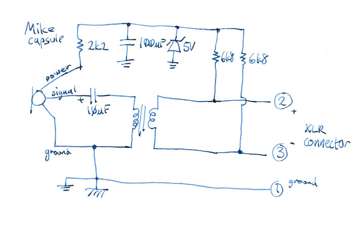
The circuit was designed for three-wire microphone connections (power, audio signal, and ground), but works just as well for two-wire mike connections, where power and audio are on the same pin (simply join them together on the schematic).
With many of the three-wire mikes, the tip of their 3.5 mm plug was audio, the ring was the power feed, and the sleeve is the ground. Some mikes have the tip and ring the other way around (simply swap your connector wiring over). Some have the tip and ring joined together, they'll work fine without changing anything. Some mikes (such as ones designed to put on a video camera) are stereo with left on the tip, right on the ring, with power supplied to each mike on top of their signal wire (you'd need two 2k2 Ω, resistors, one to each side, and two transformers).
The only critical components are the 6k81 Ω resistors. They should be very close in value, use 1% tolerance components. Perhaps find the best matching pair with a ohmmeter. They really should be that value resistor, though other close values will usually be good enough, they just need to be the same value as each other.
My transformer had different input and output impedances, I faced the high-impedance side to the mike.
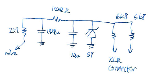
If you find that your phantom supply is noisy, or the zener diode is, you can improve the DC filtering by inserting two more components into the middle of the power circuit: a 100 Ω resistor and 10 μF capacitor, as detailed below. If you have the space, you may as well do so, even if you didn't notice any noise problems at the time.
And on that note (noise reduction), the circuit should be inside a metal enclosure that's connected to the XLR ground pin (1).
There are ways of doing this without a transformer, such as using an active amplifier circuit. Though designing a good low-noise circuit, that uses very little current, running from a low voltage supply, and can nicely handle strong audio signals, might be bit of a challenge. But many active circuits aren't actually that good at being “balanced,” though most transformers are.
Another alternative is more passive components around the mike, attempting to provide a balanced output directly. But it may not achieve that, requires 50 volt capacitors, and will have a higher output impedance. It's also harder to do outside a mike body, where the existing mike wiring is singled-ended and unbalanced.
How important is maintaining a balanced output? That depends on your environment, how electrically noisy it is. Typically a transformer output is low-impedance, as well, and that also helps with noise reduction and being able to use longer mike leads without other problems. But it could simply be that your main interest is connecting an unbalanced computer mike into a device with a proper XLR input.
Written by Tim Seifert on 8 April 2023, and last updated 8 April 2023.