Inter-station wiring
There are all sorts of ways that you can connect the different stations together, which is best will depend on your needs (robust, simple, supporting extra features, et cetera).
If you merely need an audio connection between self-powered stations, ordinary single-core shielded wiring will do.
If you also need to power the station, then the cable will need another wire (ordinary 2-core shielded microphone cable would suffice, and it allows you to use standard pre-built cables, cables that are tough enough to be dragged about). Though, using mike cables for intercom systems does run the risk of people plugging a mike into the intercom, and destroying a mike.
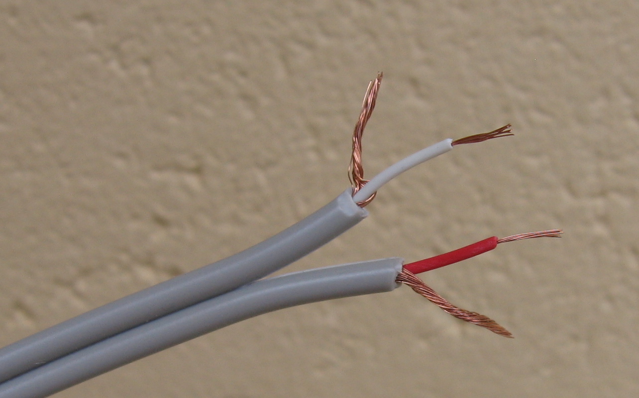
And, if you also want to send program audio, then another shielded wire will be needed. For this choice, three-core shielded wiring is less common, and can be quite expensive, but one simple and cheap option is figure-eight twin-shielded cable (where there are two shielded wires, and both wire's shields are insulated from each other), connected to a 4-pin connector. You can use one of the shields as the power supply ground, and the other shield as the positive power supply wire. For example:
- Power ground and intercom audio shield
- Intercom audio
- Program audio
- +12 volts power, and program shield.
I deliberately illustrated this with the third wire being red, to make it easier to remember which side of the twin-core cable is carrying positive voltage.
It's perfectly fine to connect a cable shield to the power supply, so long as you keep the wiring insulated from other things (so shrink-wrap the shields, slip some plastic sleeving over them, or make them very rigid with solder so they stay firmly in position). As far as audio is concerned, the power supply positive is AC coupled to the supply ground, so the shield wiring connected to either pole should work just as well. To AC, it's virtually a short circuit between the two poles of a DC supply. There's large capacitors across them, and the output impedance of a supply is very low. Though, on the off-chance that the positive supply rail has some noise on it, I'd use it for the program audio shield, and use the negative rail for the intercom line shield, to keep the intercom line as quiet as possible.
It's a cheap cable, and does manage all your wiring in one bundle. And if you use 4-pin XLRs, it's compatible with the usual professional video camera power supply wiring (where pin 1 is ground, pins 2 & 3 are ignored, and pin 4 carries +12 volts). So stations won't blow up if connected to the wrong device, stations can be tested with standard power supplies, and intercom could be wired into standard power connectors, to make them dual-function.
The advantage of 4-pin XLRs over other connectors are that they're robust, they lock together with a catch, and you make cables with a plug on one end, and a socket on the other (so you can easily extend any short cables). And you always set up the plugs and sockets in the same configuration (no voltages on exposed connector pins, so the power supply uses a female socket, and the stations have a male connector). This will (generally) be the opposite of any headsets using 4-pin XLRs (with a female plug on the headset cable), so you won't be able to accidentally plug a headset into a power supply. Users will only be able to plug the cables into the right places (headsets into the stations, stations into the intercom system).
DIN connectors are cheaper, but not as robust, and it's much harder to find chassis mounting male connectors (to maintain the rule about no voltages on exposed connector pins). DIN connections usually have female connections on all chassis sockets, with male connectors at both ends of the cable. This is a problem for cables carrying power supplies, and it's problematic to join two short cables together to make up a longer lead.
On one of our stations, we used UTP (unshielded twisted pair) ethernet cable (it's not an ethernet signal, we've just used the cable for a different purpose). We needed a very long cable, and twisted pair is good at noise rejection (when using a balanced audio circuit), though ethernet cabling isn't particular robust at being dragged around, and rarely lies flat where you leave it (so it's not the best choice for a mobile station).
We put a couple of small audio transformers in the intercom base station, one sitting across the intercom audio line and ground, and another sitting across the program audio and ground. One twisted pair of the ethernet cable went to the other side of the intercom audio transformer, another twisted pair of the ethernet cable went to the other side of the program audio transformer. Another of the twisted pairs was used to carry the intercom DC power supply. And there was a spare pair left over. Then we did the same thing inside the remote station (put audio transformers between the twisted pairs and the intercom and program audio lines inside the station).
The transformers gives us balanced audio lines between circuits that are unbalanced. Only cheap transformers are needed, as intercom audio is not a high-quality signal, to begin with.
I've kept the audio signals separate from the power circuits, rather than use phantom power over the audio lines. This avoids the situations that phantom powered circuits are plagued with; of the massively loud bangs and crackles you get with bad connections, or when someone plugs and unplugs a device. But it's certainly possible to use phantom powering techniques.
Headset wiring
There's a plethora of options for headset wiring, but some upfront hints: Try to use different types of connections for headsets than other equipment, so you can only plug the right things into the right sockets. These intercom circuits (like many others) suffer from stability issues if you do not keep the mike ground and earphone grounds completely separated. It also pays to bear in mind that a headset cable has the mike and earphone wiring very close to each other, so cross-coupling does happen in the cable, and gets worse with longer headset cables.
If you want to be compatible with other headsets, so you can borrow extra sets and not need to rewire them, or to be able to use the headsets on more than one system, you can copy some of these commonly used schemes. Many beltpack intercom systems use the 4-pin scheme, many studio cameras use the 5-pin scheme.
Do not wire anything to the XLR shells in the headset cabling. The shells will be grounded by the intercom box (if the box is plastic, then wire the intercom's power supply ground to the XLR shell). NB: Trying to use the XLR shell as a signal- or ground-carrying conductor is unreliable, but we ground the shell as a noise reduction technique.
3-pin XLR & ¼ inch jack headset
XLR
- Mike shield
- Mike + signal
- Mike - signal (balanced) / connected to pin 1 (unbalanced)
TRS
| Tip | Left earphone signal |
|---|---|
| Ring | Right earphone signal |
| Sleeve | Earphone ground |
While my intercom circuit doesn't use a balanced mike input stage, you could add an input transformer (if you needed the noise-rejection ability of a balanced input stage).
4-pin XLR headset
- Mike shield
- Mike signal
- Earphone ground
- Earphone signal
Female connector on headset, male connector on the intercom. Sometimes you may see pins 3 & 4 the other way around, and while you'll still hear audio fine (that way), it can be the cause of electronic feedback (since the earphone shielding won't be grounded). Dual-muff headsets will wire the left and right earphones in parallel with each other.
5-pin XLR headset
- Mike shield
- Mike signal
- Earphone ground
- Left earphone signal
- Right earphone signal
Male plug on the headset, female socket on the intercom. Some intercoms feed the same signal to left and right earphones, some give different feeds to each ear.