Mixer outputs
The tally outputs of vision mixers tend to be one of the two following types, open circuit collector output, or relay contacts.
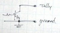
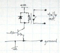
When that mixer source is going "to air," the transistor circuit will ground the tally output, and the relay contacts will close. The transistor outputs can, often, only sink a small amount of current to ground (such as between 10 and 100mA). The relay contact outputs can usually handle more current and voltage. But, in either case, you need to check the specifications of your equipment. And if it's capabilities are not enough, you build an interface circuit.
With the relay contact outputs, it may be that both contacts are electrically isolated from the rest of the mixer circuitry, or that one of the contacts is internally connected to the mixer ground, or to a common ground between all the tally relays, or that one of the contacts is connected to the mixer positive voltage. On some equipment, there is a mode switch that lets you choose how it works.
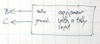
Equipment inputs
If you're lucky, you're simply going to connect a mixer tally output to an equipment tally input, and all you need to do is use the right connectors to fit into the sockets (tally signal out to tally signal in, and a common ground between them). Most equipment's tally inputs are designed for ground closure (they're “on-air” when their input is grounded). The circuits may look like one of the following, and you can build such circuits into equipment that don't already have them (using the equipment's own power supply as the tally circuit supply).
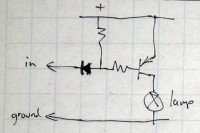
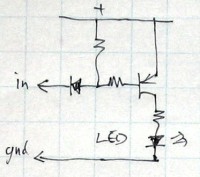
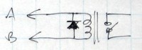
The diodes provide some isolation, so that when several tally inputs are simultaneously connected to a tally output, they don't load the circuitry down, causing tally failures.

If you find that tying multiple tally inputs to one tally output results in false tally signals, you could put diodes in the connecting wiring.
Interfaces
If you have to build an interface, there's two very basic circuits that can drive lamps, LEDs, and ground closure inputs, directly. One circuit is for a mixer that has tallies that are grounded when "on air," the other for mixer tallies that put out a positive voltage when "on air."
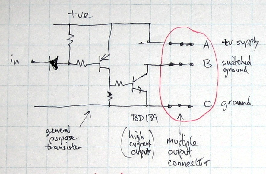
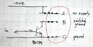
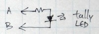
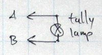
They have three output terminals, A is the positive supply voltage, B is the switched ground, and C is the ground terminal. You use two of the terminals (A & B or B & C), depending on what you're connecting to (lamps, equipment with tally inputs), and you can connect multiple devices at once (stand alone lamps, LEDs, and equipment).
The power supply is an external supply, just for the tally system. Its ground is connected to the mixer, too. Either directly, or through something like a 1kΩ resistor (low enough for tallies to work, and high enough that no large currents are going to go through the mixer).
And if you need to interface to equipment that must be electrically isolated, you can put a relay between them.
Or you could use an opto-coupler IC package (it has a light-emitting diode internally optically coupled to a light-sensitive transistor), in the same way (with it's LED being connected to the mixer tally output, and it's transistor to the other device's input). While an opto-coupler has the advantage of not being a mechanical device (potentially noisy, and subject to mechanical failure), an optical device has its own flaws (fairly limited current handling capability, limited voltage handling capability, usually only suitable for switching DC current, and must be connected with the right polarity).
A robust and comprehensive tally interface allows you to have tallies on the equipment, their control panels, their preview monitors, and other related equipment. In a traditional studio, that might be preview monitors in front of the director, preview monitors in front of the CCU operators, tallies next to the CCU panels, tallies next to the camera base units in the racks, and to the audio mixer (either as remotes for audio-follow-video switching, or simply as tally lights, with or without preview monitors, so that the audio mixer doesn't have to look into another room to see what's on air). An audio mixer may have combined tallies, so that a single lamp lights to show when any studio camera is on-air. Likewise, a studio on-air lamp, may be triggered by any camera, or any microphone, being switched on, only being disabled when all of those devices are switched off. There may be a hard-wired matrix of which individual tally sources trigger a master tally, or it may be reconfigurable on demand.
Notes
Plugs and socket types should be chosen that cannot short terminals together while being plugged and unplugged, nor when a lead is unplugged and comes into contact with other things. And use appropriate connector genders on panels and cables (there should be no voltages on connector pins, only sockets are suitable to carry voltages). If you do use connectors that can short its terminals together, or has exposed pins, as is the case with phone jacks, then your tally interface needs to be able to survive being shorted out, and it shouldn't be able to supply enough current to damage anything that it makes contact with.
Most resistors in these circuits are around 10kΩ, excepting the dropping resistors in series with LEDs (they're selected to suit the voltage driving the LED).
Lamps last longer if driven from a lower voltage than the lamp's rated for, and some lamps will even burn out very quickly when run at the voltage that they're labelled with (just general manufacturing crapness, where they market globes at battery powered torches, expecting the batteries to deliver less than the full amount). So, try running 6 volt lamps from 5 volts, and 12 volt lamps from 10 volts.
When it comes to connecting equipment with a ground closure input, sometimes you can get away with just a single wire connection, so long as other wiring between the equipment share a common ground (such as the video cables). But when connecting higher current devices, such as 12 volt lamps, wire them directly to the tally interface with two wires.
When we've modified monitors to add a tally (drill a hole, mount a LED, add a driver circuit, mount a tally socket), we've done a few things to avoid ground loops: The tally input socket doesn't directly connect to the equipment's ground, or chassis. It uses an insulated socket, with a 1kΩ resistor between the tally input socket ground to the equipment's ground. It's close enough to ground to fire up the tally if you connect the tally input pins together. And if the tally input socket is wired directly to the lamp, with no interface circuitry, then it's kept completely electrically isolated from the equipment.