The page describes the wiring of a camera, the risk of doing anything with this information is all yours, do not attempt wiring changes if you're not proficient at electronics. Be especially warned that the camera is not protected against connection to a power supply with the wrong polarity.
And because there's a plethora of variations on how different cameras, and other equipment, use the 10- and 14-pin plugs, you should only ever connect equipment together that you know are meant to work together.
Do you still use Panasonic's F15 cameras from 1991…?
NB: I don't have technical details for the power supply module which has a 10-pin CCJ on it.
4 pin S-Video socket on the side of the camera
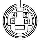
- Y ground
- C ground
- Y (luminance)
- C (chrominance)
This is a standard connector and wiring.
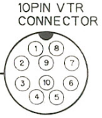
10 pin jack on the side of the camera for connecting to a VTR

- Camera video out
- Shield for camera video
- VTR serial data in
- VTR serial clock in
- Right audio out
- Record start/stop
- Left audio out
- Shield for audio signals
- Power ground
- +12 volts DC supply
This is a custom connector (and wiring) for this, and some other Panasonic cameras.
Warning: Because there's a plethora of variations on how different cameras, and other equipment, use 10-pin plugs, you should only ever connect equipment together that you know are meant to work together.
14 pin jack on the side of the camera for connecting to a VTR
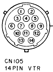
- Ground
- +12 volts DC supply
- Left audio out
- Audio ground
- Audio ground
- Camera video out
- Return video in (only works when the side-panel power switch is on 14-pin mode, and the “ret” button is pressed at the front of the camera)
- Ground
- Ground
- VTR serial data in
- Chroma out (when the side-panel 14-pin switch is on Y/C mode)
- VTR warning in (battery/tape)
- Record stop/start
- Return audio **
This is a custom connector (and wiring) for this, and some other Panasonic cameras.
Warning: Because there's a plethora of variations on how different cameras, and other equipment, use 14-pin plugs, you should only ever connect equipment together that you know are meant to work together.
Electronic View Finder / Remote connector
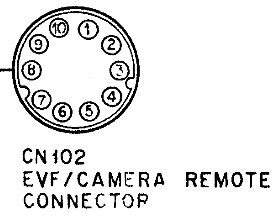
- Video out (with zebra pattern)
- Ground
- C/R serial data in/out (“C/R” may mean “camera remote”)
- C/R serial clock in/out
- Composite of standby (DC), and left (or right?) audio out (conflicting info about which channel)
- On-screen-display characters video out (no sync, very low voltage)
- Composite signal of vertical pulse, zebra pattern, and tally out (DC)
- Ground
- Ground, or not connected? (The service manual has a printing error)
- +12 volts DC out (unregulated, there's only a fuse and the power source selection switches between here, and the DC power supply inputs).
This is wired different than the WV-F10 camera viewfinder connector, do not connect F10 accessories.
The WV-CR12 remote controller, that connects to this socket, has conflicting information about the 10-pin connector. It may have a cable with differently wired connectors at each end, but I suspect a printing error about pin 9 (above).
- Video
- Shield for pin 1
- Serial data
- Serial clock & record stop/start
- Left audio & standby (DC on top of audio)
- EVF character (camera on-screen character generator to the controller)
- Zebra/tally/vertical pulse combined signals
- Shield for pin 5
- Ground
- +12 volts DC
Character Generator connector
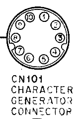
- +9 volts DC out
- External colour sub-carrier in
- External video in
- Ground
- Colour collect in
- Sub-carrier 1 out, plus DC out
- Ground
- Sync out
- Sub-carrier 2 out
- Ground
4 pin XLR jack on the WV-AD36 & WV-AD37 back ends for power supply to the camera
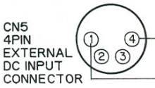
- Ground
- not connected
- not connected
- +12 volts DC
This is a standard XLR connector, and standard wiring for many professional, and prosumer, video equipment.
If you power the WV-AD36 back-end through the 10-pin connector, this connector isn't used, and is a prime candidate for modification to re-use it as a connector for an intercom. Use the spare middle two connectors, and the ground pin. The +12 volt supply pin will isolated from any power source by the back-end external/SEG power switch, but you're best not to connect headsets to that pin, in case someone plugs them into something else with a 4-pin connector (such as a battery charger), and you'll still be able to use this connector, alternatively, as a power connector, as the power cable doesn't use the middle two pins, either. You could wire these pins directly to a couple of pins in the multi-core connector, or you could fit a small intercom amplifier in the back-end between the two connectors (there is enough room, and it could run off the camera 12 volt supply).
10 pin jack on the WV-AD36 Genlock Adaptor for connecting to a SEG
- Camera video
- Shield for camera video
- (pin missing)
- Shield for genlock video
- Genlock video
- (pin missing)
- Audio from camera microphone
- Shield for audio
- Power ground
- +12 volts DC supply
This is a custom connector (and wiring) for this device. The genlock back end won't work unless powered through it using its 4- or 10-pin connector. Any power to the camera fed through the VTR connectors on the side of the camera won't power the circuitry in the back end.
We replaced this unusual connector on the back end for a common 10-pin CCJ connector, so we could re-use some old camera cables with this camera, and connect wiring for tally, line view return video, and intercom signals that were strangely omitted from the SEG connector. Since the cable carries power, it shouldn't have exposed pins, so we put a male plug on the genlock-adaptor back-end (one of the more hard-to-find CCJ connectors with a locking ring on the external part of the connector, rather than between the connector and a cable back-shell). This allows us to use ordinary male-to-female CCJ extension cables between camera and equipment.
- Camera video
- Shield for camera video
- Line view video
- Shield for line-view and genlock video
- Genlock video
- Tally
- Audio for intercom
- Shield for audio
- Power ground
- +12 volts DC supply
Warning: Because there's a plethora of variations on how different cameras use 10-pin plugs, you should only ever connect equipment together that you know are meant to work together. Though we have stuck with using particular pins to suit standard CCJ cable wiring (signals wires and shields in standard places), and for the same purposes as commonly used on some other equipment, this is a custom connector wiring, and should only be used with compatible, or similarly customised, equipment.
14 pin RCU connector on the WV-RC35 CCU and WV-AD37 back-end
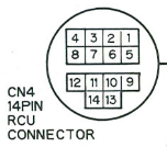
- Power ground
- +12 volt supply
- Intercom talk (CCU direct to camera operator headset mike)
- Intercom receive (CCU output direct to volume knob, then to camera operator headset earphones)
- intercom audio shields (for pins 3 & 4)
- Video out
- Video out shield (for pin 6)
- Line view & genlock video shields (for pins 9 & 11)
- Line view video
- Serial control data
- Genlock video
- Serial clock / tally in (*)
- Horizontal phase control
- Sub-carrier phase control (course phasing)
* This line is 75Ω loaded in the CCU output and camera back-end, and AC coupled through buffer amplifiers at each end (and so is the serial data line). The tally isn't a DC voltage on this pin. The tally moniker seems to have stuck from a description of how the (other) 14-pin VTR connector uses the same signal line inside the camera head, for the VTR tally. That VTR tally only works when in the 14-pin VTR mode, the CCU tally is one of the serially encoded control signals. If you want the viewfinder tally light to come on, when you don't have a CCU and WV-AD37 back-end, you need to modify the viewfinder.
This is a custom connector (and wiring) for this device. The genlock back end won't work unless powered through it using its 4- or 14-pin connector, power to the camera fed through the VTR connectors on the side of the camera won't power the circuitry in the back end.
The RCU/EXT DC power switch also acts as the local/remote selector for the coarse subcarrier and horizontal phasing controls.
Warning: Although this is the same physical connector as commonly used on old domestic Betamax cameras, it is wired completely differently.
¼-inch (6.35 mm) headset jack on WV-AD37 back-end and WV-RC35 CCU
- Tip - carbon mike (audio and power)
- Ring - earphones (medium impedance)
- Sleeve - common
The intercom headset jack uses a ¼-inch TRS phone jack, either professional or domestic phone plugs fit fine. Most carbon-mike headsets should work (1950s telephone operator sets, aircraft sets), or specially amplified headsets (some aircraft and comms sets), but any other sort of headset should have the tip disconnected, so that DC power from the CCU doesn't damage them. Carbon microphones produce a high output voltage, so you can't directly plug any other type of microphone in, and get a useful output. It'd need to be pre-amplified. One way to do that would be to use the microphone inputs on the side of the camera, and AC-couple the adjacent earphone output socket to the microphone input pin on the intercom.
The earphone amplifier in CCU is AC-coupled, to the volume pot in the back-end, which is wired directly to the headset socket, and it can drive low-impedance headphones. So a simple one-way, receive-only, intercom could use any headphone with a suitably wired plug.
4-pin intercom/tally connector on the WV-RC35 CCU
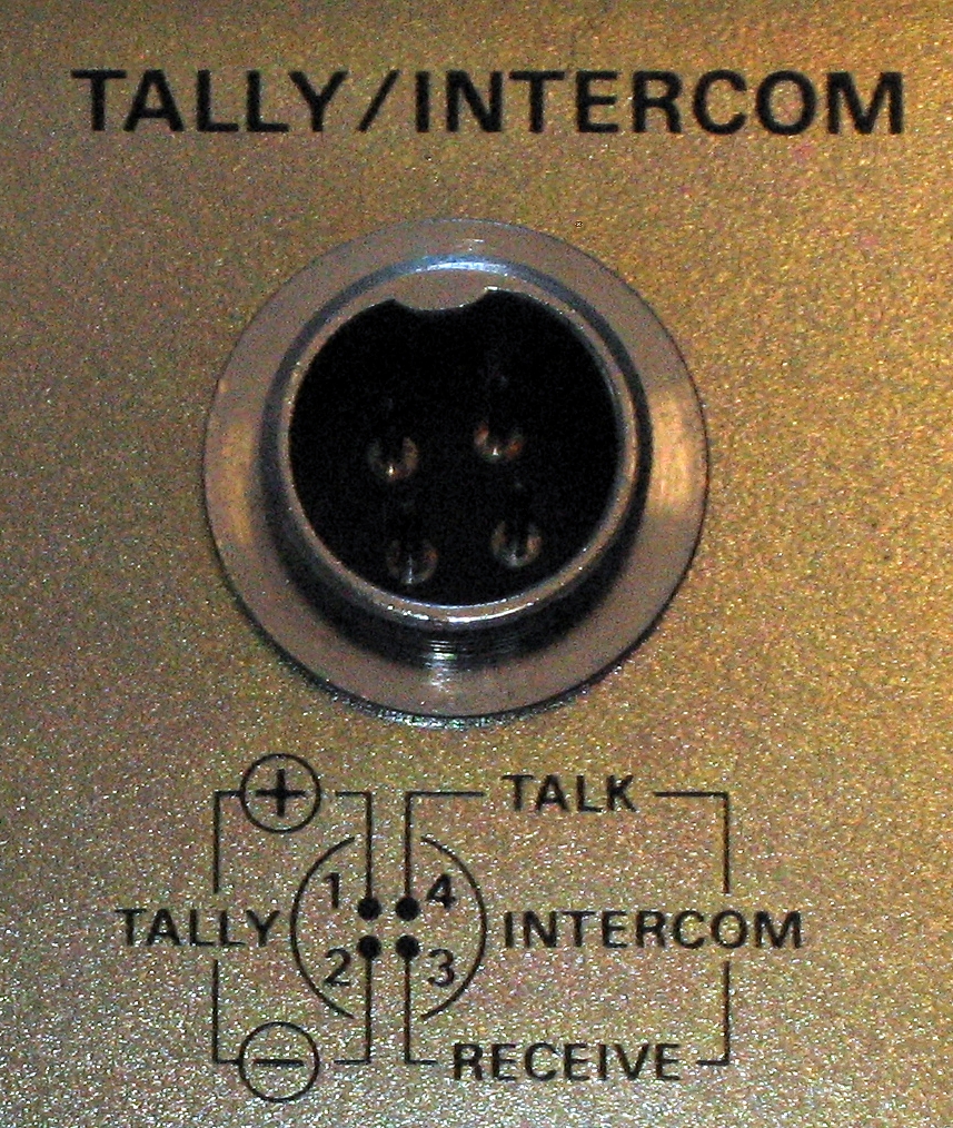
- Tally input
- Tally and intercom ground
- Intercom talk (CCU and camera talk output)
- Intercom receive (CCU and camera receive input)
This is a custom connector and wiring, commonly found across about twenty years of Panasonic video equipment. Although it looks like a common 4-pin CB radio microphone connector, the pins are narrower, and may not actually make contact with most plugs. The simple solution, if you can't get the right plug, is to swap the socket. The original plugs aren't very robust, either. Quite fine for a permanent installation, but would easily break up if continually fiddled with.
The tally input is a medium-high impedance of 33 kΩ, with a 10 kΩ pull-up up resistor to 9 volts behind the 33 kΩ resistor. The tally input is active-low, it's activated by the mixer grounding this pin (usually with an open-circuit collector transistor output). If you have a preview monitor with a similar input circuit, you could directly connect the CCU and monitor tallies together. Otherwise, you'd use a buffer circuit between the SEG tally out and the monitor tally in.
The style of intercom dates back to the use of directly coupled carbon-microphone headsets, with medium-impedance earpieces. Though this unit has buffer amplifiers between the headset jacks and the 4-pin intercom connector (for the mike and the ears), and the 4-pin connector is AC-coupled, but the signal levels are similar (the line levels similar to old analogue telephone wiring). Thanks to having a buffer amplifier, it can drive low impedance headsets (at the camera and CCU headset sockets), as well.
For a simple one-way intercom, you could feed a microphone amplifier's output (from the control room) into pin 3, and ground it with pin 1 (it's a common ground for the tally and intercom), and plug ordinary headphones into the camera back-end and CCU headset sockets, albeit with a custom-wired ¼-inch phone plug connector (the tip disconnected, the ring to the earphones, the sleeve being the common connector).
For two-way intercom, it becomes more complex. The camera and CCU can communicate together, but to talk to something else (the other camera, or the director) requires external equipment. Such as plugging all the CCUs into a desk that has the same intercom system (such as many Panasonic video mixers), and that desk being the central hub of communications.
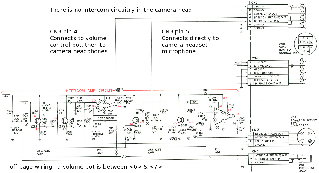
Otherwise, you can amplify the director's microphone, as mentioned above, and feed it to pin 3 of all your CCUs. And feed the CCU & camera intercom audio output of pin 4 into a headphone, or loudspeaker, amplifier in the control room. You bridge all the pin ones together, pin threes together, and all the pin fours together. You shouldn't get feedback, as the CCU doesn't mix the audio going to them with the audio coming back from them (you can view an image of the CCU intercom circuit). The cameramen won't be able to directly talk to each other, as they're not electrically mixed together, but they will be hear each other accoustically, via the loudspeaker in the control room. This does, at least, make it less likely that two of them will try talking to you at the same time.
You can mix some of the CCU's talkback send and receive together, this is what's done in many Panasonic video mixer's intercom circuitry. But you shouldn't just wire the pins together, you stand a good chance of causing feedback. And you definitely will get feedback, if you use loudspeaker intercom monitoring in the control room.
As an alternative to using an amplifier and loudspeaker in the control room, if you have camera preview monitors with audio amplifiers built into them, you could connect each CCU's pin 4 intercom audio output into that camera's preview monitor's audio input. Then when the cameraman talks back to you, his voice comes out of his preview monitor. This gives you a simple, and intuitive, way to control the volume of each talkback channel.
Running loudspeaker intercom monitoring in the control room has the advantage that control room crew don't need to wear headphones, nor would one person with headphones have to relay information to those without them. But has the disadvantage of making things noisier. Using headsets in the control room is a problem for those who don't have a set, and for those who need to listen to some other audio at the same time.
Unfortunately, like many simple cameras, its intercom is rather quiet, and hard to hear in some situations. So you may want to ignore it, and use an external intercom; or modify the built in one. We find that the intercom is inadequate, and doesn't suit other equipment that we use, so we use our own custom intercom circuit.