One of the problems with electronics is that they're easily damaged by reverse polarity of the supply voltage. The usual way of protecting against this is using polarised plugs that can only fit one way around, but that gets defeated by diffferent power supplies that use the same kind of plug with the connector being wired up in the reverse direction. And people manage to put batteries in the wrong way around, despite there being mechanical obstacles to that in the battery compartment.
There are a few common solutions this issue. One is to wire a diode across the input so that if the polarity is reversed it will blow the fuse. The trouble is that this is destructive, and people will replace blown fuses with a wire that won't blow. An improvement is to use self-resetting polyswitches instead of fuses. And it's still no guarantee to protect the equipment (the fuse doesn't blow instantly, the diode isn't a perfect conductor, and if the diode dies so does the protection). If the fuse has blown successfully protecting the equipment, it may be a good idea to replace the diode.

This type of protection is commonly found in equipment that bothers to include reverse polarity protection, but it's kind of rare for equipment manufacturers to bother to include any protection.
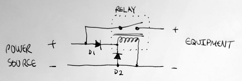
An alternative is to use a relay in series with the supply that is only switched on when the power is applied in the right polarity. This ensures the equipment is only ever powered up with the right polarity. In the following schematic, D1 only energises the relay when the power is correctly applied, and D2 handles flyback current from the coil when its de-energised.
There are some drawbacks, though:
The relay coil uses some power, so you wouldn't want to use this with battery powered equipment, unless there is a manual power switch between the battery supply and this circuit. The relay shouldn't cause significant battery drain, though you can put a resistor in series with the coil to reduce its current, but it will continually drain the battery even when the equipment is not in use.
The relay contacts are not a perfect conductor, and can cause some loss, particularly with age and heavy current. And very heavy current can weld relay contacts together.
I've seen solid-state versions of this circuit, where a power FET was used instead of a relay. The source and drain are in series with the supply voltage, and a diode going to the gate is used to turn it on when the correct polarity is applied. I've never created this kind of circuit, so I don't have an example schematic, but I'm sure you can search Google for a power FET reverse polarity protection circuit.
For low-current circuits, and where external voltage regulation is not a concern, a simple diode in series with the power source can be sufficient. It'll certainly protect from reverse current, but this method has its own drawbacks: Since there is a voltage drop across the diode, it's not suitable for devices that need a precise supply voltage, and the diode will get hot with heavy current use.

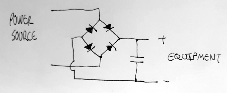
And if diode losses aren't a concern for you, you can use a bridge rectifier to make a circuit where there'll always be correct polarity power to your equipment, no matter what polarity source comes from the power source, even alternating current. I've built the following circuit into some portable audio signal level meters (which had their own built-in voltage regulators), I can run them from any suitable voltage power supply I have to hand (in this case I used AC transformers, as the simplest, most reliable, and quietest power supply for them).