The page describes adjusting the circuitry of a camera, the risk of doing this is all yours, do not attempt this if you're not proficient at electronics. If you don't understand the terminology on this page, or aren't familiar with the normal appearance of video waveforms, you're probably not ready to attempt these procedures.
I strongly recommend you get your hands on the service manual for this camera. I bought a reasonable copy of it from the user-manuals.com website. It provides a wealth of useful information about the camera, it's one of the older styles of manuals that also describe the principles of operation. The basic things that you're likely to want to tweak are the level gains, automatic white balance, white balance presets and gains for the automatic tracking white balance, and the colour encoding. You will need test equipment to do this.
The signal level gains, and white balancing, can be done with a oscilloscope or waveform monitor, but you really want a vectorscope, as well. And you really should have a YWV2310RB99 logarithmic greyscale test card. The colour encoder alignment really needs a vectorscope, and a YWV2100RB98 colour test card (though the procedures only makes use of the red and yellow test colours).
Since the test cards are expensive, and would have to be imported, I settled for some bright yellow and red objects I had to hand, and compared the scope display between a known good F250 camera, and the F15 camera I was adjusting, using a split screen through an analogue video mixer (digital mixers will introduce their own colour decoding and re-encoding errors). Likewise with comparing skin tones, and some other difficult colours (any colours that you notice looking very different between different cameras and real life). Not the best of methods, but then I was trying to make the F15 camera fit in with other cameras, so there's some logic in aligning one camera to match the other. You can never fully achieve that, especially with industrial and cheap prosumer cameras, even more so when you're trying to match together different models of cameras (as they have different sensors and circuitry), but you can tune out the more grossly obvious differences.
To make a colour chart, your best approach would be to get some pure red and yellow photographic pop filters, and fix them (separately) in front of a white card. The Panasonic colour chip test card is built that way (with the other four primary and secondary colours, too). Any other way (paints, photographic paper), gets knobbled by the reflectivity, hues, and saturations of your colour test objects. Just the same as how something looks different on your monitor versus looking at it with your eyes, there's different spectral responses and sensitivities involved. Each medium is different.
You'll need a colour temperature conversion filter for aligning the auto-tracking white balance (it's done with typical studio and outdoor lighting colour temperatures). Kodak 80B, Fuji LBB-12, Kenko LB-120, Hoya LB-120, and Nikon B12, are listed as suitable filters in the service manual.
Unless stated otherwise, illuminate the test cards with a standard 3200 K video floodlight, for all measurements. Make sure that the room lighting is dim, or off, so that there are no colour temperature inaccuracies. Likewise, take care to avoid reflections of other coloured objects and light sources into the test area. The manual says to illuminate the test cards with 1400 lux, or 140 footcandles. Leave the camera on auto-iris, unless otherwise directed, with the external auto-iris control at the centre detent position. Unless a procedure calls for deliberate exposure errors, the alignment must be done with properly exposed video.
The AGC (auto gain control) switch should be off. When the procedures say to turn gain off, low, or high, it's referring to the user's control switch on the camera body. There isn't an internal switch, and the camera should be disconnected from any CCU during adjustments.
After finishing aligning the camera, independently, you can reconnect the CCU. If any aspects of the camera's output change when connected to the CCU, you'd need to repair or modify the CCU, particularly if you had multiple cameras and CCUs that you might randomly connect together. The CCU only has internal adjustment trimpots for adjusting its voltage regulators, all the other controls are external.
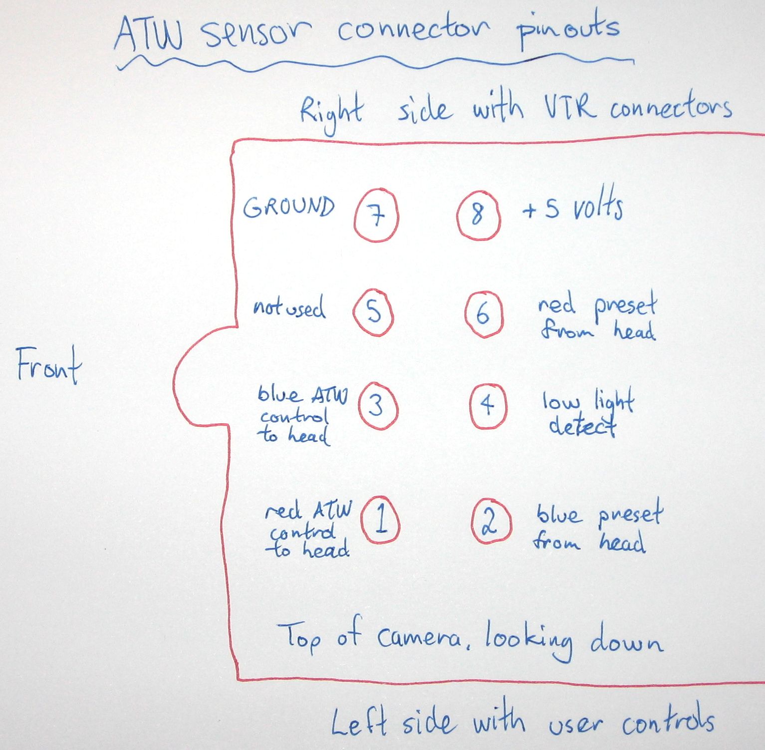
White balance mode should be left on ATW. If it's changed to AWC, during any adjustments, then it should be reset to ATW for the next set of adjustments. ATW adjustments can only be made when there's the ATW sensor fitted above the lens, the ATW is completely dependent on it. With the exception of fitting a shorting plug into the ATW socket, and repurposing the ATW mode as a fixed whitebalance preset (see the adjacent illustration for the connector pinouts, input pins 1 & 2 need joining to ground pin 7). This grounds the ATW control inputs, stopping them from setting red and blue gains in an excessive manner, beyond the range that other controls may be able to compensate for. Some non-ATW adjustments also have the same requirement, because they depend on the camera being in ATW mode (with a properly white balanced picture). So fit the ATW sensor, or a substitute shorting plug, for the entire alignment process, and leave it there for normal camera operation. For multiple cameras and ATW sensors, it's best if you always use the same ATW sensor with the same camera that was aligned against it.
The manual white balance controls, externally accessible through the side panel, should be switched off.
SES (strobe effect shutter) should be disabled.
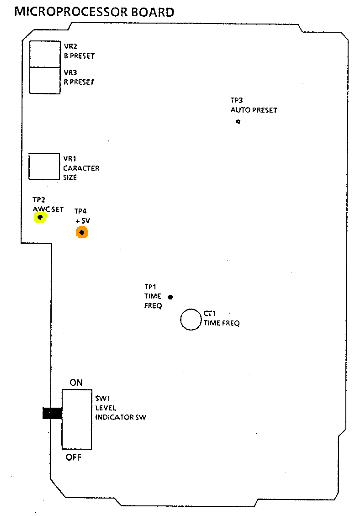
Some tests require jumper leads on test points that will set some of the required operating modes. Grounding TP3 on the microprocessor board, forces ATW mode, low AGC, and SES off. Also on the microprocessor board, supplying 5 volts from TP4 to TP2 forces continual AWC, virtually the same as keeping your finger on the AWC set button. However, when this is done while in the ATW mode, the AWC controls are forced to preset levels, rather than actually doing a white balance.
At times I've mentioned average and difficult filming scenes. I'm referring to scenes with an overall average contrast well within the contrast range of video, versus scenes with lowlights, small highlights, and small portions of overexposure (such as filming someone in a room with a window behind them, and some reflections on things in the room), and mixtures of different colour temperature lighting.
Stating the obvious, but if you find that a measurement already corresponds with the notes here, then don't adjust the controls. I've coloured some of the layout diagrams to aid with the instructions, below. But the actual boards don't have colour-coded parts, nor even any names on the trimpots. And unless otherwise indicated, when monitoring the video outputs of the camera, the monitoring devices should be properly terminated with 75Ω, but internal measurements at test points must be high impedance (unterminated).
Common alignment problems
Every F15 camera that I've come across has had the following problems: The auto-iris over-exposes, even on shots with an overall average bright picture content. The white-clip level is far too high, causing any over-exposed highlights, or even the entire picture, to go well above legal video levels (there is no white-clip control, so you'll need to adjust video gains differently than the original manual procedure outlines). The chroma level is too high, causing over-saturated pictures, and even causing colour-clipping. The colour encoder is usually out of balance, and phase, causing colour flicker and peculiar colours. The automatic white balance doesn't quite get it right, the difference between cameras is is quite noticable in multi-camera studios, even more so thanks to the chroma being too high. The colour bars are out of phase with the camera video output (this camera doesn't generate bars, internally, and feed them through the camera's colour encoder; instead, externally generated bars are fed in the back, and the video output switched between bars or camera).
The service manual's alignment procedure doesn't fix up some of these issues, particularly correct exposure, excessive video above white clip level (well above 100% IRE), and over-saturated chroma. So this page has customised procedures to fix those errors up.
To properly align any camera, you need to know what the standard video specifications are, to tell when you're aligning the camera correctly. Even more so when a service manual would have you set up a camera to produce out of specification video, which will cause you problems.
| Sync | 0.3 volts peak-to-peak |
|---|---|
| Burst | 0.3 volts peak-to-peak |
| Blanking/black level | the same as the top of the syncs |
| White level | 0.7 volts above blanking |
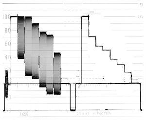
The adjacent diagram shows two lines of colour bars, the second without the chroma on top of the luma. Though it's marked in IRE units (0% to 100%, from black to white level; and down to −40% for sync tips below the black level) rather than in voltages.
Shortened alignment procedures
Assuming that the camera is mostly okay, but just a bit of out alignment (e.g. the white balance between different cameras not matching very well), you may be able to get away with just doing the following steps (the various sections below this part of the page), in the listed order, skipping over some sections when they're already okay (like I recently did with some 1990s-vintage cameras that have probably never been maintained since they left the factory). Otherwise, you'll want to get your hands on the full service manual (not from me, I provided a link to one source at the top of the page). Simply put, you're going to reset the auto-iris to get nominal exposure (the external user controls can be used to customise the auto-iris for different lighting conditions, but manual iris control is a better solution), reset the output gain to get normal sync levels, reset the input gain to get normal video output levels, reset the zebra to give sensible over-exposure warnings, reset the colour encoder, and reset the white balance.
If you won't be able to connect an oscilloscope to internal test points, but will be able to monitor the normal video output sockets, then I'd suggest a few adjustments be made first, ahead of the alignment sequences described in the sections below; and don't alter them, again.
-
Adjust the video output level to get standard 0.3 volts sync. This will set the rest of the video output signals, proportionally, to the correct levels.
-
Adjust the video input level to get normal 1.0 volts white clipping levels while over-exposing the camera.
Play around with the iris and zoom to try full screen over-exposure, and only small sections of the image being over-exposed, until you're happy with white clip levels that aren't significantly above 1 volt with partial screen over-exposures, but aren't too significantly under 1 volt when large portions of the screen are over-exposed (the camera output drops when most of the screen is white). Small overshoots above 1 volts due to aperture correction video peaking are allowed. Whacking great big chunks of over 1 volt video are not. They'll get white clipped by some equipment, other equipment will reduce the overall picture gain (you'll lost contrast, very badly), or other distortions may occur.
See the video levels section for where to find the controls. Then, you'll be able to adjust things like auto-iris, auto gain, encoding, chroma levels, and white balance, while monitoring the normal video output connectors.
Auto iris level control
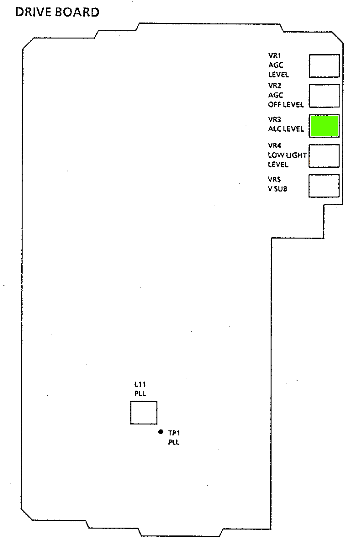
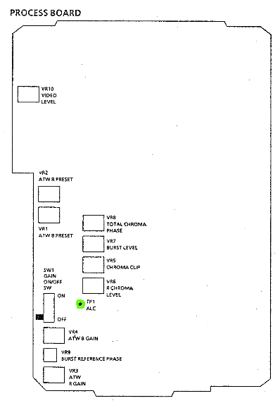
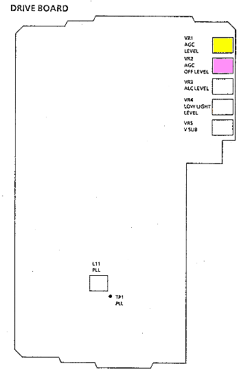
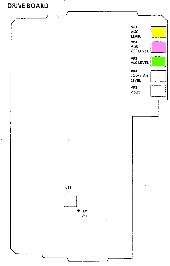
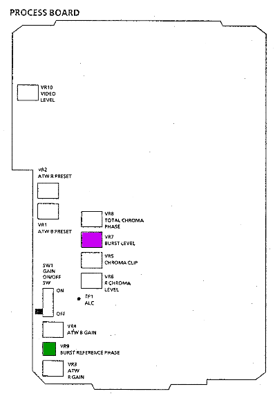
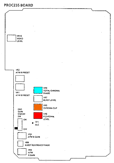
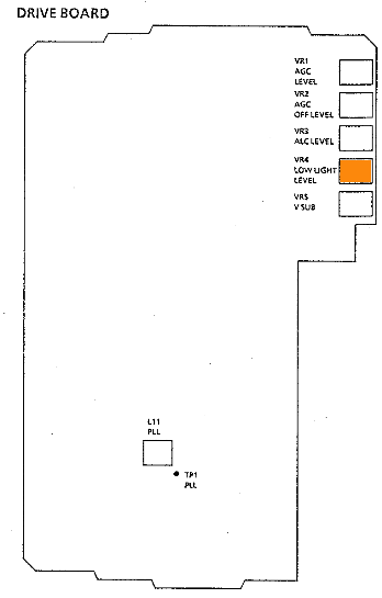
Film a greyscale card, connect an oscilloscope to TP1 (ALC) on the process board (highlighted with the green ring), adjust the ALC trimpot VR3 on the drive board (highlighted with green) to read 0.2 volts peak-to-peak from the blanking level to the brightest section of the greyscale.
This adjustment should really be done with the AGC turned off, or at least trialled with it on and off, so you don't have one automatic thing working against the other.
After you've finished doing all the alignments mentioned on this page, you may want to change this setting to get the auto-iris to expose well on average, and some difficult, pictures. I find the cameras tend to over-expose on most scenes, and under-expose on bright scenes. With the AGC turned on, it's almost impossible to get proper exposure on some scenes, where it would be appropriate to reach full exposure, or for it to be a naturally dark scene.
If you don't have a proper test card, then you need something like it (white, black, and medium gray), then tweak while filming a scene with a overall average luminance, and some people to use as test subjects.
Automatic gain controls
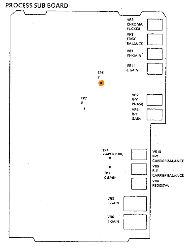
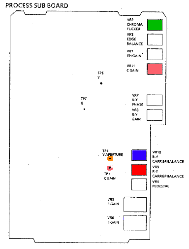
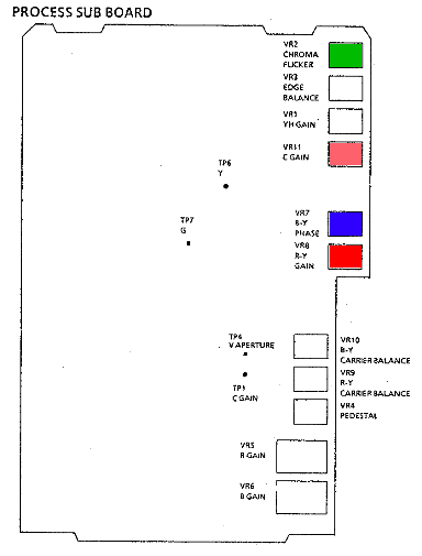
Turn off the auto-preset mode, so you can use the AGC switch. Film the greyscale card, connect an oscilloscope to TP6 (Y out) on the process sub-board (highlighted with orange ring). Switch the AGC off, and adjust VR2 (AGC off fixed gain level) on the drive board (highlighted with pink), for 0.15 volts peak-to-peak from the blanking level to the brightest greyscale level. Switch the AGC to low, and adjust VR1 (AGC level) on the drive board (highlighted with yellow) for the same reading.
If you need to tweak auto-gain levels afterwards, you can simply monitor the camera's normal video output, to adjust for normal signal levels.
Pedestal
Cap the lens, turn the AGC off, connect an oscilloscope to pin 3 (Y out) of the S-Video connector, and adjust VR4 (Pedestal) on the process sub-board (highlighted in grey) for a 35 mV pedestal level.
The norm for PAL video is no pedestal level (pedestal the same as blanking), though cameras are often adjusted for a very slight one, to aid viewing under-lit scenes, or to cope with design issues with the camera. The choice is yours, but it's generally best to align a camera to specification, then use CCU controls for artistic modifications. You can also make this adjustment while monitoring the normal video output of the camera, this makes it easier to use a standard waveform monitor to align for normal pedestal levels.
Aperture correction (artificially increased picture sharpness)
If your picture is abnormally soft (check the front and back elements of your lens, first—I've come across several where there's something smeared over the inside of the back element, which causes depth-of-focus to become very shallow), or overly crispened, you may want to perform this adjustment, otherwise skip it.
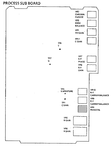
Film the greyscale chart, and on the sub-process board, use a dual trace oscilloscope to monitor TP4 (aperture, highlighted with orange ring) and TP7 (G signal, highlighted with green ring) while adjusting VR3 (v.edge balance, highlighted with orange) for minimum aperture waveform signal and keeping the G signal at 0.5 volts peak-to-peak from blanking level to the brightest step of the greyscale.
Video levels
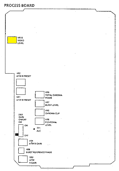
Film the greyscale card. Connect an oscilloscope to pin 32 of the 32 pin connector on the back of the camera, and adjust VR1 (YH, the video input gain) on the process sub-board (marked in yellow) so that scope reads a 0.7 volt peak-to-peak signal from the blanking level to brightest greyscale section. Then connect the oscilloscope to the video out socket, terminate the socket with 75Ω, and adjust VR10 (video level) on the process board (marked in yellow) for the same reading.
I modified this procedure to get a correct video output from the camera (as the original procedure's alignment would let over-exposure extremely overdrive the video output, way above the proper white-clip level) to these steps: Connect the oscilloscope, or waveform monitor, to the video output socket. Film a test card, turn off the AGC, and over-expose the picture until white-clipping occurs. Adjust the process board VR10 video output level trimpot to get standard 0.3 volt peak-to-peak syncs (this trimpot controls overall signal level output). Then adjust the process sub-board VR1 video input luminance level so that white clipping occurs at the right place (1 volt peak-to-peak of video, from sync tip to white level, or 100% IRE).
You may, also, have to play with AGC and ALC (auto-iris) presets, on the drive board, to get sensible pictures when the auto controls are in effect. The camera defaults to auto-gain and auto-iris in stand-alone (no CCU) mode, and tends to make poor judgements (under-exposing average scenes, over-exposing difficult scenes).
I have several WV-F15 cameras that lower the white clip level, and the video gain, on very over-exposed scenes, where a large portion of the picture is over-exposed; or let the white clip be too high on scenes with just a few over-exposed highlights in the image. Making it impossible to get the exposure you wanted, even with manual settings, under some circumstances. But another (later WV-F15HS model) camera didn't change its white clip level along with the average picture level.

Chroma encoder output
Chroma gain: Film the colour test card, switch AGC to low, connect an oscilloscope to TP1 on the process sub-board (highlighted with a pink ring), and adjust VR11 (C gain, highlighted in pink) so the burst signal is 0.22 volts peak-to-peak.
Chroma flicker: Film the colour test card, monitor the camera video out with a vectorscope, and adjust VR2 (C flicker) on the process sub-board (highlighted in green) for minimum flicker.
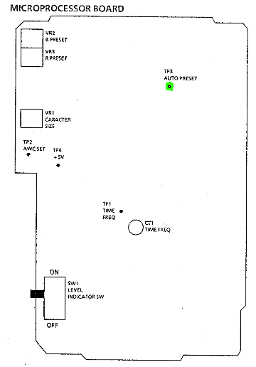
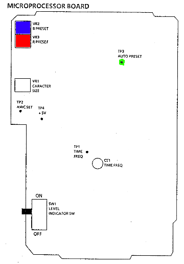
Carrier balance: Cap the lens, monitor the camera video out with a vectorscope, connect TP3 (auto preset, highlighted with a green ring) on the microprocessor board to ground, and adjust VR9 (R-Y) and VR10 (B-Y) on the process sub-board (highlighted in red and blue, halfway between mid-board and the bottom of the board) to centre the picture vectors (you should only see normal burst vectors). Unground the test point when completed.
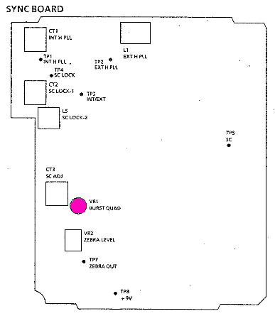
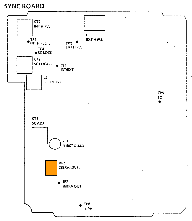
Burst balance: Monitor the camera video output with a vectorscope in NTSC or PAL+ mode (automatic inversion of the alternated vectors, to give an NTSC-like display), and adjust VR1 (burst reference) on the sync board (highlighted in purple) so that both burst vectors have the same amplitude, landing on top of each other.
Burst
Burst gain: Monitor the camera video output with an oscilloscope or waveform monitor, terminate it with 75Ω, and adjust VR7 (burst level) on the process board (highlighted with purple) for standard burst level (0.3 volts peak-to-peak, or half way down the sync tip)
Burst reference phase: If you do not have the WV-AD37 RCU adaptor back-end, skip this routine. Attach it to the camera, and power the camera through it. Connect the camera video out to one channel of a vectorscope. Supply black burst to the WV-AD37 back-end genlock input looped through the other channel of the vectorscope. View the camera video output on the scope, with the scope synced to the black burst source. Place the WV-AD37 camera/bars switch on bars, and adjust the vectorscope phase for a normal vectorscope display. Change the camera/bars switch to camera, and adjust VR9 on the process board (highlighted in green) so that the camera's vectorscope display vectors are rotated into the same (normal) positions. You're phasing the camera output to match the colour bars generated within the WV-AD37 back end. (This camera is weird for not having an internal colour bar generator, and piping bars through from an external source. For that reason, you need to align the camera to the bar generator, or you'll never be able to properly phase up the camera by using the bars when you're genlocking—the bars would be in phase, and the camera out-of-phase. Because of this, if you put different back-ends on your cameras, you want to label which back-ends belong with which cameras, so you only have to make this adjustment the once.)
Automatic white balance
NB: If re-aligning the colour encoder afterwards, you will probably have to re-do this step, again, before aligning the auto-tracking white balance. This step needs performing before adjusting the colour encoder, so it may be unavoidable to do it more than once.
Film a greyscale or white set card, connect TP3 (auto preset) on microprocessor board (ringed in green) to ground . Adjust VR2 and VR3 (blue and red presets) on the microprocessor board to white balance the camera. Use a vectorscope and/or waveform monitor or oscilloscope on the video output to monitor your adjustments. Remove the ground from TP3 when done.
The test point is hard to get to, and you may not be able to pull the board out, and it's probably best if you don't, so reach between the boards using a long insulated-hook probe. The test point is a pin on the track side of the board, about the middle of where the shielded box is on the component side.
As this test makes an adjustment with the camera in ATW mode (forced by grounding test point three), there either needs to be an ATW sensor fitted to the camera, or a shorting plug fitted to the ATW sensor socket.
Chroma encoder input
Before adjusting chroma encoding, the auto-white balance procedure (above) needs to be performed. And will need re-doing after the chroma encoding procedures.
If the colour hues between this camera and another look the same, you should skip these steps. But if you find that coloured objects look quite different, even when the cameras are properly white balanced, you probably need to adjust these camera signals going to the colour encoders.
Film the colour test card, monitor the camera video output on a vectorscope in NTSC or PAL+ mode (alternating vector is inverted to give an NTSC-like display), connect TP3 (auto preset) on the microprocessor board (highlighted with a green ring) to ground. Turn VR5 (chroma clip) on the process board (highlighted with orange) fully counterclockwise to disable chroma clipping. Then do the next three steps, repeating as necessary, until the required results are achieved (there is interaction between the adjustments).
-
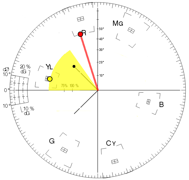
Adjust VR6 (chroma gain) on the process board (highlighted in red) so the yellow test vector chroma level is 146% (±5%), compared to burst amplitude.
-
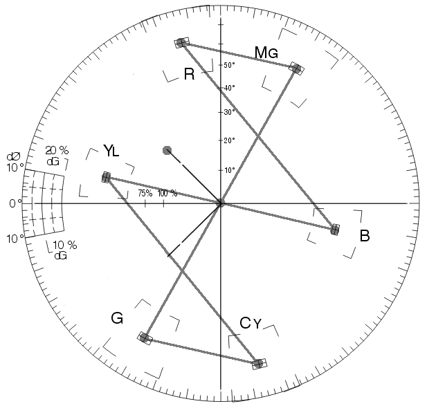
Adjust VR8 (R-Y gain) on the process sub-board (highlighted in red) so the red test vector chroma level becomes 175% (±2%), compared to burst amplitude.
-
Adjust VR7 (B-Y phase) on the process sub-board (highlighted with blue) so the red phase of the red test vector becomes 106° ±1%
See the adjacent diagram for an explanation, and you can click on it to see a bigger version. The vectorscope is in the 75% bars mode, as indicated by the burst vector dot. The red dot shows the amplitude and angle to adjust the red vector for. And the yellow dot shows the amplitude to adjust the yellow vector for, with the yellow wedge showing the angle that it may appear in (the angle isn't defined, and filming a test card with a camera won't produce ideal vectors like a colour bar generator does). This, also, assumes that the test card is ideally exposed. Otherwise, if underexposed, the vectors may appear closer to the centre. Or, substitute test objects may produce vectors in quite different locations. This is where it's handy to be able to do A:B comparisons between two cameras, though it may be impossible to adjust the F15 camera to produce the same results as a different model of camera (I have a F15HS camera that won't produce the same alignment as a F15 camera, never mind completely different models of camera).
If it's impossible to make the adjustments, or match the camera with another using these adjustments, you may need to tweak some other chroma settings, as well: On the sub-process board VR11 (C gain, highlighted in pink) for overall chroma levels, with VR2 (chroma flicker, highlighted in green) to stabilise the flickering vectors. And/or VR8 (total chroma phase) on the process board (highlighted in cyan), to skew some the vectors around, so that all the vectorscope chroma dots align in the right boxes (for PAL, it's easiest if you use a scope that lets you invert the alternate dots, so that they converge on each other, and you get an NTSC-like display).
Then, film a greyscale testcard, monitor the camera video output on a waveform monitor, over-expose the camera, and adjust VR5 (chroma clip) on the process board (highlighted with orange) to minimise carrier leak on the over-exposed portion of the video signal, so all chroma is cut off where the camera is white-clipping.
(Colour television was so much easier when all your camera outputs were RGB into the vision mixer, and you had just one chroma encoder at the output end of the vision mixer…)
Automatic white balance (repeat)
If you've just adjusted the chroma encoding (the above procedures), then you'll need to re-do these automatic white balance adjustments. If you haven't, then skip this section, it's exactly the same as the first time you set the automatic white balance.
Film a greyscale or white set card, connect TP3 (auto preset) on microprocessor board (ringed in green) to ground . Adjust VR2 and VR3 (blue and red presets) on the microprocessor board to white balance the camera. Use a vectorscope and/or waveform monitor or oscilloscope on the video output to monitor your adjustments. Remove the ground from TP3 when done.
The test point is hard to get to, and you may not be able to pull the board out, and it's probably best if you don't, so reach between the boards using a long insulated hook probe. The test point is a pin on the track side of the board, about the middle of where the shielded box is on the component side.
As this test makes an adjustment with the camera in ATW mode (forced by grounding test point three), there either needs to be an ATW sensor fitted to the camera, or a shorting plug fitted to the ATW sensor socket.
Automatic tracking white balance
Film a white test card, while monitoring the camera video output with a vectorscope and/or waveform monitor. Ensure that the your light also spills onto the ATW sensor. Connect TP2 (AWC set) to TP4 (+5 volts) on the Microprocessor board (ringed in orange and yellow), remove the link between these test points when you've finished all the ATW alignment procedures. All the trimpot adjustments, will be made on the process board.
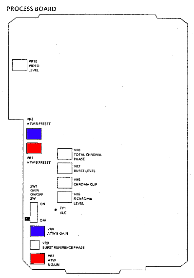
Under 3200 K lighting conditions, very slowly adjust the two mid-board red and blue ATW preset trimpots, VR1 and VR2, to white balance the camera. There will be sudden change as you move away from the correct alignment, you're making adjustments in the middle of a feedback loop.
Gel the light, or the camera lens and ATW sensor together, for daylight conditions (5600 K), and adjust the two bottom of the process board red and blue ATW gain trimpots, VR3 and VR4, to white balance the camera. There may only be minimal affect as you adjust the trimpots.
The ATW alignment seems very finicky, and you may have to repeat these 3200 K and 5600 K adjustments a few times. You may want to take the camera outdoors into real daylight, and back into 3200 K studio lighting, to ensure that it works correctly. I had to repeat these steps a few times, indoors and outdoors, and I also tested with mid-day and dusk (extremely blue) lighting conditions. Without the extra fiddling, it would only work under indoor or outdoor lighting, but not both. There would be extremely wrong tints, otherwise.
With very blue daylight, the camera may not have enough range to be able to white balance. This is a limitation of doing electronic-only colour temperature compensation. For alignment, you may have to do it during normal daylight hours. For actual late evening filming, you might have to forgo white balancing using ATW, and put 85A or 85B colour correction filters on the lens; or try use ATW with a 85A or 85B filters on the lens, and another taped over the sensor.
I think the manual has mislabelled the the ATW red and blue presets the wrong way around, though it doesn't really matter, as you have to adjust both of them to set the white balance. I've highlighted the red and blue preset trimpots on the diagram (below) according to the colours that I see actually being adjusted on the vectorscope.
Obviously, if you do not have an ATW sensor, you cannot do these alignments for it. However, you can preset the camera for a useful fixed white balance when set to ATW mode. You need to build and fit a shorting plug into the ATW sensor socket (above the lens), and leave it there as a permanent installation. Then adjust the ATW gain trimpots on the process board for your desired preset. The ATW preset pots are no-longer connected, so you can ignore them. See the white balance page, for more information.
Exposure level indicators
Connect a viewfinder that gives you lowlight and zebra pattern displays, either the WV-VF02 1″ eyepiece viewfinder, or the WV-VF65 5″ viewfinder with the WV-Q39A mounting bracket (the WV-Q39 bracket doesn't pass through the on-screen-display messages used to display a low-light warning), and monitor the video output with a waveform monitor or oscilloscope.
Turn off the auto-preset mode, set the AGC to high, underexpose the image, and adjust VR4 (low light level) on the drive board (highlighted in orange) so that the warning comes on when you consider it suitable. Just under 50% exposure level would be a good point. The on-screen “LOW” light warning text will only appear when a working AAA battery is fitted in the holder in the right side of the camera (the flat, or no battery, “BACKUP” warning prevents the low light warning from appearing).
Turn off the AGC, turn on the zebra pattern switch on the sync board, and adjust exposure so that you have a image that includes portions that go right up to full video level. Adjust VR2 (zebra level) on the sync board (highlighted with orange) so that the zebra pattern draws on the viewfinder picture just before over-exposure occurs. Around 95% full signal is a good point, this allows you to use the zebra to avoid white-clipping and over-exposure where it matters, and show where it's nearly full white, without cluttering the viewfinder.
Test modes set by jumpers on test points on the Microprocessor board
Grounding TP3 forces ATW mode, low AGC, and SES off.
Supplying 5 volts from TP4 to TP2 forces continual AWC (virtually the same as keeping your finger on the AWC set button). However, when this is done while in the ATW mode, the AWC controls are forced to preset levels, rather than actually doing a white balance.