![[photo of CCU]](/video-production/instructions/images/wv-rc35-front-panel.jpeg)
Cable compensator fine-tuning
The cable compensator has a four-position coarse-adjustment switch that affects signal gain and high-frequency peaking, and a fine-adjustment control that affects the high-frequency peaking, but has no fine-adjustment control for the gain. And, unfortunately, the coarse-adjustment switch doesn't accurately adjust the gain for the lengths of cables it supports, it's out by quite a large amount (probably due to component tolerances—we have four CCUs, and each is different).
You could change the fixed resistors switched in place for each position of the switch (R31 for 10 metres, R33 for 40 metres, & R35 for 70 metre cables), to correct the errors, but it's difficult to do that with SMD resistors (there's not much space for stringing combinations of resistors together), and results might change with temperature and time (so what seems like it might be the most convenient modification, as far as using the CCU goes, might not end up being the best approach). It's easier to replace R30 with a pot, as it affects all positions of the switch, giving you the traditional fine-adjustment control for gain. Replace it with a 10 kΩ pot wired as variable resistor, rather than a voltage divider, with a 1kΩ fixed resistor in series, so the normal position of the pot is around the centre of travel. R30 is the 6.2 kΩ resistor near the edge of the board, between CN12 and a SMD transistor.
Since we do have different cables, it's useful to be able to quickly change the compensation, so we fitted an external control (re-using the hole where the intercom headset goes, as we don't use the rather awful intercom built into the CCUs). If you don't change cables, then an internal trimpot could be good enough, to fix up the settings, once. If you want intercom and complete cable compensation controls, then you're faced with drilling another hole somewhere. I'd suggest moving the coarse-adjustment switch to the back panel, as you only need to set that with a change in cable length, which you can do when patching cables, and you avoid messing up the front panel. You want the fine tuning controls on the front panel, where they're easy to access.
NB: Cable compensator gain shouldn't be used instead of camera gain adjustment. Camera video gain control is (properly) done before gamma correction in the head, compensation gain is after this point. You could, also, end up creating illegal video that's greater-than one volt, as the cable compensator gain is after the white clip circuitry in the camera head, too.
Intercom
The built-in intercom system is rather inadequate, and designed to work with carbon headsets. Replacing it is fairly easy, there are two shielded wires in the multicore that go to the back-end on the camera, with only a volume control between the wiring and the headset socket, so you can simply re-use the wiring with your own intercom system.
14 pin RCU connector on the WV-RC35 CCU and WV-AD37 back-end
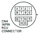
- Power ground
- +12 volt supply
- Intercom talk (CCU direct to camera operator headset mike)
- Intercom receive (CCU output direct to volume knob, then to camera operator headset earphones)
- Audio ground
- Video out
- Video out ground
- Line view video
- Line view ground
- Serial control data
- Genlock video
- Serial clock / tally in (*)
- Horizontal phase control
- Sub-carrier phase control (coarse phasing)
* This line is 75Ω loaded in the CCU output and camera back-end, and AC coupled through buffer amplifiers at each end. The tally isn't a DC voltage on this pin. The tally moniker seems to have stuck from a description of how the (different) 14-pin VTR connector uses the same signal line in the camera head, for the VTR tally. That tally only works when in the 14-pin VTR mode, the CCU tally is one of the serially encoded control voltages. If you want the viewfinder tally light to come on, when you don't have a CCU and WV-AD37 back-end, you need to modify the viewfinder.
NB: On the camera head, in the section between the camera and where the WV-AD37 back-end plugs into, below the 32-pin connector is a +/− “run” switch. It's obvious purpose is to do with the polarity of the record-pause start/stop signal. However, it also affects the CCU operation, and needs switching up to the + position for the CCU to work. Otherwise, most of the camera head and CCU controls are disabled.