There are some design flaws with these VTRs that can be compensated for with some modifications, as well as some customisations that some people may want to do.
- Overzealous drop-out compensator
- Noise/hash on the audio
- Annoying blue screen
- Adjacent video monitor interference
- TBC blanks out VITS
- TCG blanks out VITS
- Can't adjust the tracking control far enough, or the centre click-stop position doesn't match the VTR's own tapes
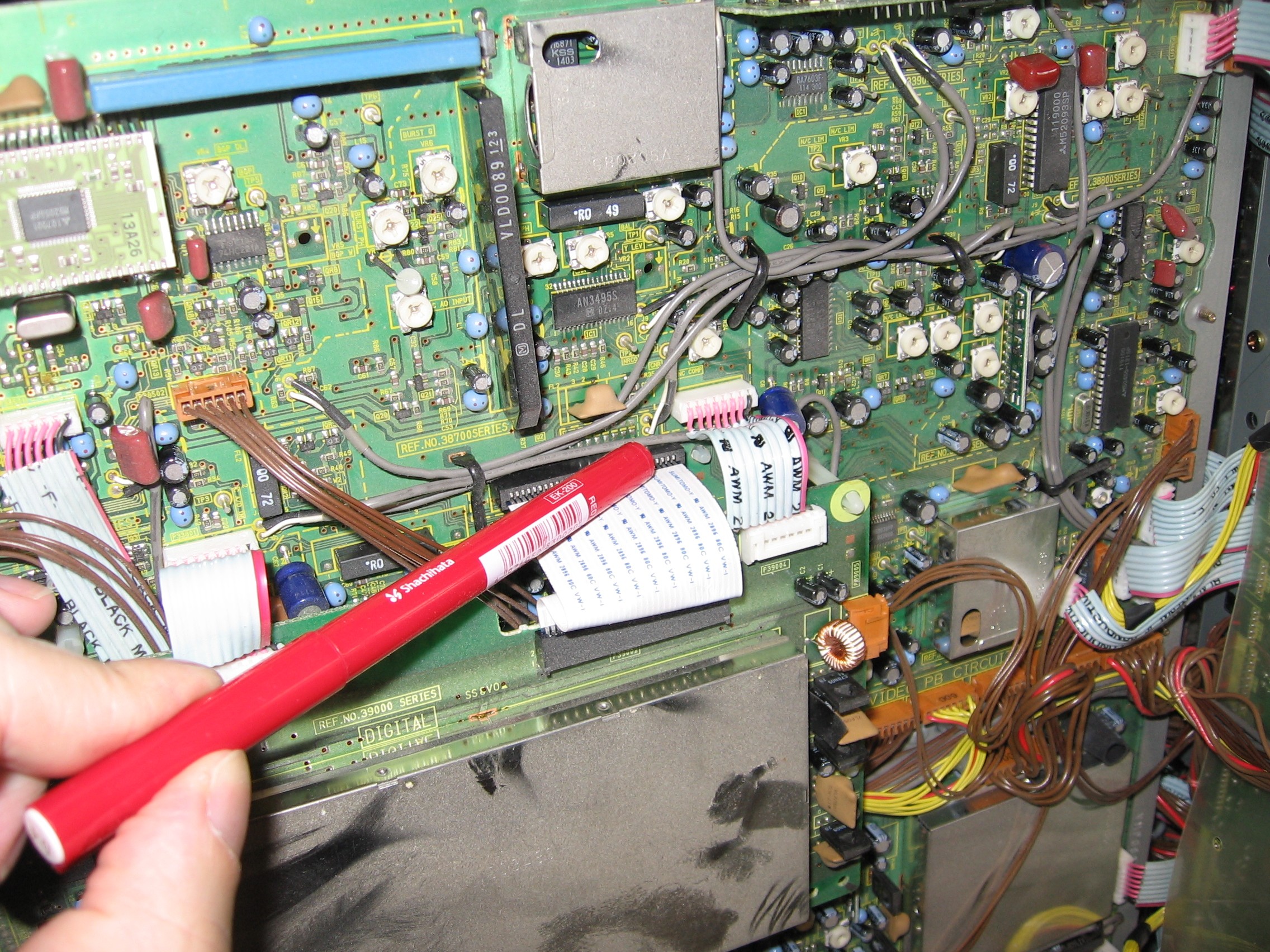
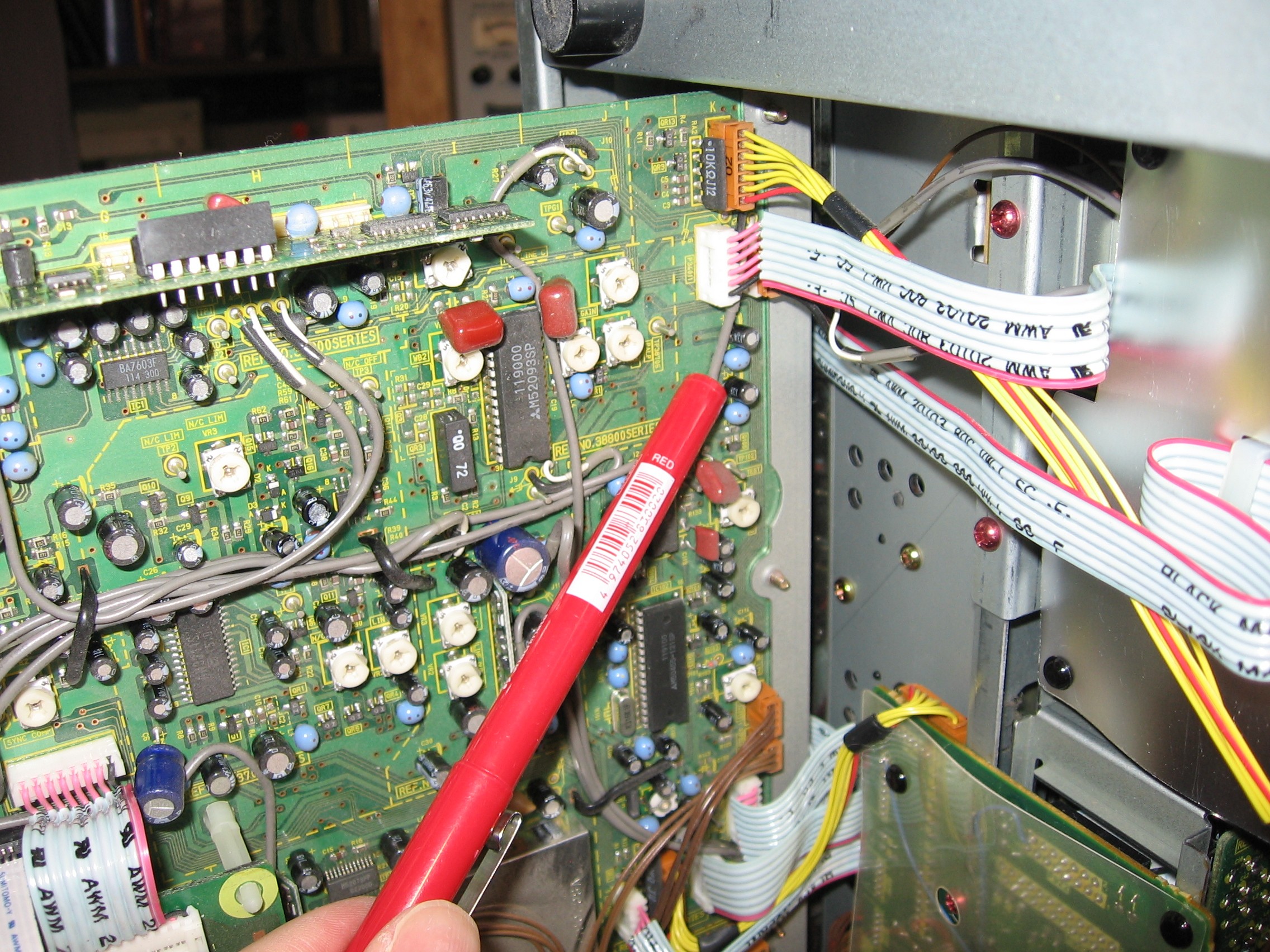
NB: The small circuit board pictures on this page are links to the full, large, pictures, which show more of the board around the points of interest.
Drop-out compensator (DOC) freezes bottom of frame
A drop-out compensator covers up tape drop-outs by replaying a line, or more, of previous video over the top of a missing line of video. This could be from a line above the current line, or from a previous field or frame—it depends on how the particular DOC works, and how bad the drop out is. It measures the amount of RF from the tape playback, and switches into compensation mode when the level drops by a certain amount. For small drop-outs, a repeated line of video may be barely noticeable, or less objectionable than random black & white noise.
Unfortunately, these VTRs don't let you turn off, nor adjust the threshold of the DOC, not even as a service adjustment (the manual shows trimpots on the board layout, but they're not in the circuit diagrams, nor on the actual boards). And, worse still, these VTR's DOCs have a nasty habit of freezing the entire frame below a small drop-out, which looks horrible on any panning shots, or any other shots with lateral movement in them. So users resort to turning off the TBC, forgoing the other advantages that it provides (correction of time base errors, which will not be fixed up by digital/analog hybrid video mixers that you might be connecting the VTR through, and the proc-amp controls). There are two better alternatives:
-
You can remove the signal that triggers the drop-out compensator, so it never triggers. This is easily done, as the DOC signal passes from a small board mounted in the middle of the video playback board (one of the large boards in the base of the VTR, below the mechanism), to a connector (P34004) on the edge of the video playback board, via a thin shielded cable. (That P34004 connector goes to the TBC boards.) Disconnecting that shielded lead, will disable the DOC, but you'll lose the advantage of having a working DOC. And this portion of the DOC detection is working correctly.
-
Or, you can modify the DOC trigger on the TBC board, so it doesn't freeze the rest of the frame. This is easily done by changing one resistor on TBC board two. Change R492, above IC491, from a 33KΩ resistor to a 68KΩ resistor (around location C1, according the legend printed around the edge of the board). This is the faulty (by design) section, and fixing this gives you a properly working DOC. See the picture, above, the blue resistor is my replacement for the bad original R492 SMD resistor.
It might be possible to add in a DOC threshold control, but I don't really want to try and trace out the PCB layout diagram, to work out the differences between the layout, the schematic, and the version that was actually built. And the second modification (mentioned above) has worked well, for me, since the early 1990s.

Noise/hash on the audio
I've not experienced this, myself, but after making comments on my newly bought edit suite (back in 1991), that were passed back to the manufacturer, about how the Dolby Noise Reduction was (like many badly designed tape decks) mostly removing lots of playback amplifier noise, more than it was having to reduce any (relatively smaller amounts of) tape hiss, and that better designed playback audio amplifiers would be a big improvement, I got a reply enquiring whether I was hearing some other noise generated by the machine. Apparently, some machines have the internal audio interconnection leads loomed together with some other interconnection leads, and splitting them apart eliminates the induced noise.
It should go without saying, but I've seen people make this silly mistake, that if you sit a CRT video monitor on top of the VTR, or too close to it, it's likely to induce noise into the VTR from the video monitor. This can make a mess of your video production, putting buzzes into the sound, or interference patterns on the picture. Likewise with placing other equipment on the VTR. You're fairly safe stacking two of the same VCR on top of each other, as the location of noise producing parts, and noise sensitive parts, will be the same in both of them (e.g. the power supplies are at the back, away from the heads and boards).
Annoying blue screen when there's no signal

Yes, as well as Window's blue screens, many Panasonic VTRs and TVs will show a blue screen upon loss of signal. Those of us in TV studios with equipment running 24/7, or other long hours, don't like having our monitor's blue phosphors worn out much quicker than the red and green phosphors, so we find this allegedly “useful feature” annoying. I have a modification that changes it to show a dull grey screen, instead. I'm not sure if it's possible to make it go completely black, I've never tried, this modification was good enough for me.
On the video playback board under the mechanism, there's a M50455 character generator, IC4102, about two thirds along the edge of the board that hinges out from the bottom of the VTR, and about an inch in, on the side of the board that faces into the VTR. There's a circuit going from pin 19, to a resistor (R4142, 1KΩ), to a capacitor (C4132, 27pF), to an inductor (L4108, 47µH), and back to pin 17. You could cut a track, or remove a component in that circuit, to remove the colour portion of the background video.
Adjacent monitor interference
When two CRT sets are placed right next to each other, the magnetic fields from one can affect the other, particularly when they're each showing asynchronous video sources, and one of them has its horizontal scan frequency different than the other.
Related to the above blue screen issue, is how the “lost signal” blue screen is generated, by a simple character generator without a well adjusted oscillator—it free-runs at a rate different than normal video. So, when a machine is stopped, its monitor may scramble the picture of another monitor sitting next to it.
It should be possible to tweak the character generator's oscillator, to make its horizontal scan rate closer to normal. There's an adjustable trimcap (CT4101, 20pF) next to the M50455 character generator (IC4102) that should do the trick. Read the blue screen issue notes, to locate where this IC is.
It should go without saying, but I've seen people make this silly mistake, that if you sit a CRT video monitor on top of the VTR, or too close to it, it's likely induce noise into the VTR from the video monitor. This can make a mess of your video production, putting buzzes into the sound, or interference patterns on the picture. Likewise with placing other equipment on the VTR.
The TBC blanks out any VITS
The TBC is set to blank out the entire vertical interval period (during playback), and that will eliminate any VITS that you might want to see, as well as any VITC. There is a switch on TBC board three, just above the edge connector towards the front of the VTR, that controls whether to blank out the vertical interval (“mute” position) or output all the blanking period (“all” position).
The TCG blanks out any VITS
When the optional time code generator board is installed (take off the top lid, the board is mounted above the cooling fan), it has a switch that will delete all lines (ALL DEL set to ON) in the vertical interval period (when recording), allowing just the VITC signal there, or just blank out the lines that the VITC generator inserts into (ALL DEL set to OFF).
You would need this set on if the incoming video already has VITC on it, and on different lines than the VTR's VITC generator will use, otherwise you'd have two sets of conflicting time code. Or you'll need to make sure that your VITC generator inserts its time code over the top of the same lines.
You can find out what lines have time code on, during playback, by putting the remote/local switch on remote, and holding down the counter reset button. The line numbers will be shown on the front panel display, and the video monitor's on-screen-display. You won't see your VITC generator's signal inserted into the vertical interval of the picture until the record button is pressed (it can be STOP and RECORD, it doesn't actually have to be recording), or during a video insert edit.
On the other hand, you'll need it turned off if you want VITS to be recorded. In this case, you will need to make sure that the VTR's VITC generator is inserting its time code over different lines than the VITS, and over the top of any incoming VITC (so you don't get two different sets of time code).
Tracking control
The tracking control is normally set at the centre click-stop for playing back tapes recorded on itself, but sometimes the machine alignment has drifted, and it will always need setting at a different position. The tracking control preset can be adjusted to re-centre the control.
Or, you find that when adjusting the tracking control for best picture playback, that the knob doesn't turn as far around as you'd like to be able to turn it. Again, the tracking control preset can be used to re-centre the control. Unfortunately, this may need adjusting more often than you'd care to, as the tracking control doesn't seem to have the range needed, to adjust either way, to deal with other tapes.
Take off the top lid, the preset is found on the edge of the servo board, under the plastic-covered foil shield (attached with three red screws), just behind the video head drum. It's VR2003, or VR3, marked “TRAC-FIX.” Set the front-panel tracking control to the centre click-stop, then adjust the preset. Normally, when all is well, both controls are close to their centre positions.
I haven't, yet, looked into increasing the range of the control. It might not be possible. The obvious approach (decreasing the trimpot) doesn't appear to increase the range, it just moves the offset. I think the external pot would have to be changed for a 200KΩ one, and the internal trimpot turned down to 0Ω